
Circuit Design
The circuit diagram of this project is shown below. A 5V relay is driven by a PN2222 transistor that is controlled by RB3 pin of PIC16F628A. Digital inputs from the 4 push buttons are read through port pins RA2, RA3, RA4, and RB0. The functions of these push buttons are discussed in the operation section below. A standard 16×2 character LCD is used in the project to display the device status, program menu and time. The LCD is operated in 4-bit mode, therefore, only 6 I/O pins of PIC16F628A are required to drive it. A piezoelectric buzzer provides audible tone when the timer is started and stopped. It also beeps when the device is turned on or off. The + 5V power supply for the circuit is derived from a LM7805 regulator IC. The input to the regulator is given from a 9V DC wall adapter.
In the circuit diagram, the pins 15 and 16 of the LCD are shown open. These pins are available only in those LCDs that have a back light illumination LED. The pins 15 and 16 are the anode and the cathode of the LED. If your LCD has the back light LED, you can connect these pins to the power supply terminals with a 39 Ohm resistor in series. The backlight LED enhances the readability of the LCD display in low illumination condition.
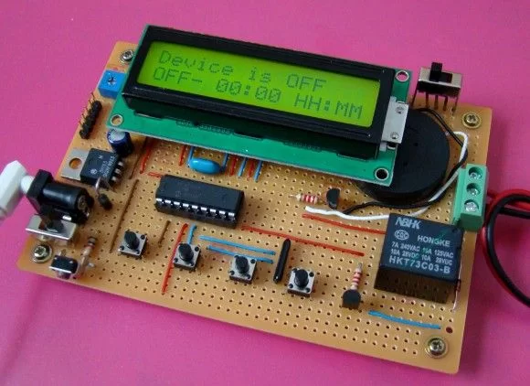
The complete circuit soldered on a general purpose prototyping circuit board is shown below.
Operation of the timer
The timer gets inputs from the 4 push buttons. Their functions are described as follows:
About The Author
Ibrar Ayyub
I am an experienced technical writer holding a Master's degree in computer science from BZU Multan, Pakistan University. With a background spanning various industries, particularly in home automation and engineering, I have honed my skills in crafting clear and concise content. Proficient in leveraging infographics and diagrams, I strive to simplify complex concepts for readers. My strength lies in thorough research and presenting information in a structured and logical format.
Follow Us:LinkedinTwitter