| ||||||||||||||||||||
Radio-controlled (R/C) modelling seems to fascinate many electronics enthusiasts. This technical hobby is a melting pot of many interesting disciplines, including mechanic engineering and electronics. Many ‘modellers’, and especially newcomers, start from largely pre-assembled models or kits which allow them to build a model boat, car or airplane without too much of a risk. All battery-powered models have one aspect in common: the speed control is based on a variable resistor which is operated by a servo motor. Anyone who has used such a model for some time will discover that the variable resistor may run pretty hot, which means that a lot of energy is wasted in the speed control. A shame, really, because the storage and retention of sufficient energy to power just about any vehicle is still one of the biggest problems in model building. Fortunately, there exists a much more efficient alternative. The present circuit demonstrates an intelligent and low-loss motor controller which may be built from relatively few parts. The result: one battery charge will allow the model to drive, fly or sail longer. Because the circuit is relatively easy to construct, improved efficiency does not come at high cost in this case. Moreover, the size and weight of the circuit are modest, which is an important aspect in this context.
 A SEAMLESS TRANSITION
As a matter of course, the electronic motor controller was designed to comply with standards which are widely used in radio-controlled model building. After all, keeping to the conventions is the only way of making sure that the existing regulator may be replaced by its modern electronic counterpart. The mechanical speed regulators which are normally fitted in ready-made models are controlled by a servo motor. The servo, in turn, is controlled by pulse-width modulated signals supplied by the radio receiver installed in the model. The pulses that form the servo control signal have a width between 1ms and 2ms. In this system, a width of 1ms corresponds to ‘maximum’, 1.5ms, to ‘mid-travel’, and 2ms, to ‘minimum’. These pulses are sent every 40ms (i.e., at a rate of 25Hz). The servo used has an important function because it translates the received pulse width into a corresponding movement of a lever, which changes the setting of the variable resistor via small rod. As a result, the motor voltage increases or decreases, causing the model to accelerate or slow down. The all-electronic version described here replaces the servo, the lever, the rod and the variable resistor in one go. Apart from eliminating the energy waste inherent to a traditional regulator system, the circuit also saves space and weight in the model.
The motor control may be built in two versions. For model planes, the control is used in unidirectional mode (i.e., as an ordinary min./max. regulator). The entire control range is then used to adjust the speed of the propulsion motor over a large range. The second version operates as a bi-directional control. This type will be used mainly in model boats and cars. The span of the control is then divided into two ranges: ‘forward’ and ‘reverse’. The centre position of the control then corresponds to ‘off’, i.e., the motor does not run. Because this ‘zero’ point is rather critical, a certain ‘dead’ span has been created around it. This is done to prevent the motor reversal relay from ‘chattering’. Because this relay is normally fitted in the vehicle, it is not found back in the circuit described here.
A motor braking function has been implemented in unidirectional mode. At the zero setting, this brake short-circuits the motor, allowing the reverse emf (electromotive force) generated by the motor to rapidly reduce the speed of the model to nought. To make sure that the interface and the used transmitter work happily together, the minimum and maximum propulsion power may be programmed, in addition to the previously mentioned dead zone. In this way, the microprocessor’s power is fully exploited.
THE APPROACH
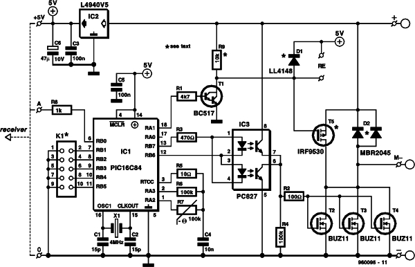
The complete circuit diagram of the motor control is shown in Figure 1. The schematic includes all components for unidirectional as well as bidirectional use. The desired version is chosen before building the circuit. Your choice therefore determines the components used. The circuit has been kept as compact as possible. The result: a motor control weighing less than 25grammes.
Figure 1. Circuit diagram of the R/C model motor controller. The heart of the circuit is a RISC microprocessor from Microchip Technology Inc.
The (intelligent) heart of the circuit is formed by a PIC microprocessor (type PIC16C84-04) from Microchip Technology Inc. This miniature RISC processor contains all elements needed for the project. Because control signals always consist of logic levels (pulse width modulated logic signals are found at the input as well as the output), the speed control does not require an A/D converter.
The connection to the receiver is made via a three-wire link, which is standard in model building. In addition to the control signal (A), the interface also receives its supply voltage (+5 volt and ground). In other words, the receiver gets its supply voltage via the motor control.
The control signal supplied by the receiver is applied directly to pin RB0 of the microcontroller (IC1). The other inputs of the microcontroller (RB1-RB5) are connected to pinheader K1, for use during the configuration of the circuit.
Three outputs are significant in the process of controlling the motor speed. The signal used to switch the direction relay (bidirectional version) or the motor brake (unidirectional version) is available at output RA1. Opto-isolator IC3, a type PC827, is driven via outputs RB6 and RB7. The opto-isolator, in turn, drives the transistors that determine the current through the motor. Because high currents are not uncommon in model building, three MOSFETs type BUZ11 are connected in parallel here, the triplet allowing currents of up to 40A to be handled without problems.
As already mentioned, you have to decide on the function of the circuit before you start building it. In the bidirectional version, components T5 and R9 are omitted. In the unidirectional version, D1 and T1 are not required.
The motor is connected between the two terminals marked + and M-. In the unidirectional version, a diode type MBR2045 (D2) is found across these terminals.
This dual Schottky diode has been specifically developed for heavy-duty applications, each diode being able to cope with a current of 20A. In this circuit, the MBR2045 acts as a flyback diode to suppress voltage surges generated when the motor is being switched. Diode D1 is the flyback diode which is connected across the relay.
The battery voltage is transformed into a stable voltage of 5V by an integrated regulator. The 5-V rail is used to power the motor control as well as the receiver. An NTC (negative temperature coefficient) resistor, R7, allows the motor and battery temperature to be monitored. The value of the NTC resistor is calculated by charging capacitor C4 alternately via R6 and R7. Because the value of R6 is known, the resulting time differences allow the value of R7 to be calculated. At the selected switching thresholds (defined in the software), the protection is actuated at 120°C and switched off again at 80°C. If the protection is not required, the NTC may simply be omitted. The resistance is then, in principle, infinite, which, as far as the controller is concerned, corresponds to a cold motor or battery.
CONSTRUCTION
Now you know the theoretical details of the circuit, you are ready to start building the actual thing. The track layout and component mounting plan of the printed circuit board used to build the control are shown in Figure 2. As already mentioned, compactness was a prime issue during the development of the circuit. The PCB is double-sided, and has components at both sides. Where possible, SMDs (surface- mounted devices) have been applied.
Figure 2. The double-sided board guarantees a compact construction. Components are fitted at both sides!
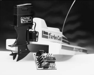
Figure 3. The finished prototype demonstrates the meaning of ‘compact’. Thanks to the use of PIC processor, the unit weighs only 23grammes.
Before you start soldering, you have to select between unidirectional and bidirectional mode, because that determines the component content of the circuit. For unidirectional mode, D1 and D2 are omitted, while T5 and R9 are mounted. opposite applies if the circuit is used in bidirectional mode.
Start by fitting all SMDs at the copper side of the board. This should not be too difficult or time-consuming if you use a fine-tipped soldering iron. Next, you turn the board around, and carefully fit the parts at the top side. If you want, you may fit IC1 and IC3 in sockets. A 10-pin header is used for K1. Heatsinks are not required although pretty large currents may flow in the output stage. None the less, if high currents are a reality, it is recommended to strengthen the copper tracks through which the current flows. In practice, that is easily achieved by soldering a short of thick, solid copper wire onto the relevant track section.
The connections for the supply voltage, the motor, the NTC and the relay are made via solder pins. After inserting the programmed microcontroller into its socket, the circuit is ready for use. Because noise generated by, for example, the motor may upset the operation of the control, it is recommended to fit three 100-nF (0.1-µF) suppressor capacitors across the motor. One capacitor is connected between the two motor terminals, and the other two, between the motor terminals and the motor housing (ground). Finally, we recommend winding the wires that carry the drive signals from the receiver to the control through a ferrite bead (two or three times), as close as possible to the receiver.
Figure 4. The circuit may be used to replace the mechanical speed control in virtually any model, be it a boat, car or plane.
| JP1 | Maximum forward speed. | |
| JP2 | Maximum reverse speed. | |
| JP3 | Minimum forward speed | |
| JP4 | Reset (When closed during powerup) | |
| JP5 | Mode. 1 = Unidirectional, 0 = Bidirectional. |
 MISCELLANEOUS MATTERS
The mode of the circuit is selected with the aid if jumper JP5.
Fitting it selects unidirectional mode, omitting it, bidirectional mode.
In unidirectional mode, set the joystick on the transmitter to minimum speed, and temporarily close jumper JP2 (approx. 1second).
This enables the PIC processor to couple the received pulse time to minimum motor speed.
Next, set the joystick to maximum, and briefly close jumper JP1.
This links maximum motor speed to the received pulse time.
The microcontroller then automatically ensures that the entire speed range is coupled to the span of the control signal.
Roughly the same procedure is followed for the adjustment of the bidirectional mode, only jumper JP2 is then used to determine the maximum reverse speed. Also, the dead zone may be programmed as an extra. Set the joystick to the position which you still want to be interpreted as ‘zero’, i.e., the highest joystick position that causes zero motor activity later. Briefly close jumper JP3. The controller will record this setting and store it into its memory. All settings are stored in an EEPROM, which allows them to be retained for a long time. A reset during which the default settings are loaded is accomplished by closing jumper JP4 and then switching the supply on. The controller then loads its (internally defined) pre-programmed values (defaults), and all user-programmed values are overwritten.
The speed control may then be fitted into the model and connected to the motor, the receiver and the battery. If you want to make use of the NTC, the component may be fitted on to the motor or the battery. You may then look forward to many happy hours racing your model car, sailing your boat or flying your plane.
(960095-1)
COMPONENTS LIST
Resistors:
R1 = 4kOhm, SMD
R2 = 100Ohm, SMD
R3 = 470Ohm, SMD
R4,R6 = 100kOhm, SMD
R5 = 10Ohm SMD
R7 = NTC, 100kOhm
R8 = 1kOhm, SMD
R9 = 10kOhm, SMD
Capacitors:
C1,C2 = 15pF, SMD
C3,C5 = 100nF, SMD
C4 = 10nF, SMD
C6 = 47µF 10V SMD
Semiconductors:
D1 = LL4148*
D2 = MBR2045CT*
T1 = BC517
T2,T3,T4 = BUZ11
T5 = IRF9530
IC1 = PIC16C84 (order code 966510-1)
IC2 = L4940V5
IC3 = PC827
Miscellaneous:
K1 = 10-way pinheader
X1 = 4MHz quartz crystal
Printed circuit board and programmed PIC (IC1): set order code 960095-C
PIC also available separately: order code 966510-1
For more detail: motor controller for R C models