MintLite – The Luxeon Powered Mint Tin Flashlight!
This idea has been rattling around in my head for more than a month now, and I finally have thought it out enough to do some doodling in Eagle. The basic idea is built around a six watt Luxeon K2. I plan to use a pair of 2.5aH lithium batteries to provide approximately eighteen watt-hours of power. The Luxeon will be controlled by a microcontroller, providing different brightness levels, as well as protecting the luxeon from excessive current when the batteries are fully charged. The microcontroller will also monitor the battery voltage; dimming the light as needed and eventually shutting down completely to prevent over-discharge. The light will contain it’s own battery charger, powered by USB using the MAX1811. The MAX1811 will charge a single lithium cell (or cells in parallel) at up to 500mA off a self-powered USB port. The 1811 allows charging from a bus-powered port as well, but for sake of simplicity, I will ignore that option.
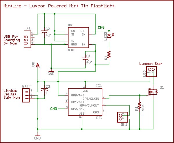
The circuit keeps things fairly simple. Switch Q1 provides pwm control of the luxeon. Header SW1 will connect to some sort of switch, for turning the light on and off, and changing brightness. The MAX1811, IC2, takes 4.3 to 6.5 volts as input, and regulates it to 4.2 volts for charging the lithium cells. Charging status is indicated by LED2, which will light when the charger is in bulk charging mode (current mode).The microcontroller, IC1, is a PIC12F683. The 683 provides a lot of bells and whistles for such a small chip. I will be using analog input 0 to monitor the battery voltage. General purpose input 2 will monitor the charging status, perhaps to disable charging when the batteries are in bulk charging mode. General purpose input 4 will use an internal pull-up resistor to monitor the switch. General purpose output 5 is controlling a mosfet transistor responsible for PWM of the led.
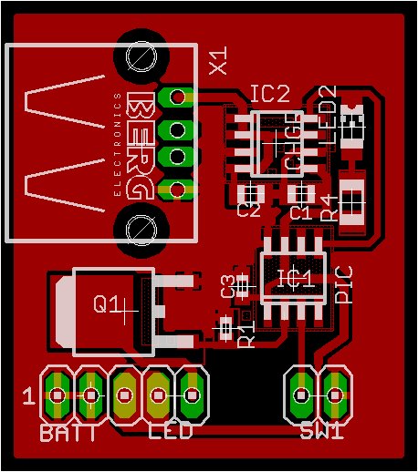
The pcb layout is in it’s early stages, and designed mainly around parts I have on hand. I don’t think I’ll actually prototype this PCB, since it’s much too large, and the wrong shape. Whether it gets printed or not, it was fun to draw. There are two main things I want to change. First the FET (Q1) in the TO252 package is rated at something like sixty amps – way more than I need for this project. ON Semiconductor has some nice SOT23 fets rated at 4 amps that should fit the bill nicely, and save a lot of space. Secondly, I need to find a smt version of the usb connector, perhaps a mini usb instead.
Hopefully this weekend I’ll be able to breadboard this circuit and see how it all goes together. Stay tuned for “Part II”.
For more detail: MintLite Part I
