Sales Pitch
Are you confused by choices? Who isn’t? There are just so many things to decide. White, rye, or wheat? Pinstripes or polka dots? Feast or fast? Well, don’t worry because help is on the way!
I’m introducing the world’s first, portable, hand held, decision maker powered by truly random numbers. Sure, my competition has long sold decision makers for 1, 5, 10, or 25 cents. But can they decide between more than two choices? NO! Are they really random? NO! NO! My decision maker can choose between up to 16 options, and the results are truly unpredictable, according to the postulates of quantum (or at least statistical) mechanics.
 Now, I hear some of you object, “But Leon, I can make decisions on my own.” Perhaps, but they’re often arbitrary, illogical, and regrettable. Why agonize over both the choice and the results, when you can just worry about the latter? Try something new! Stop worrying! Tell determinism to take a hike! Destroy the paradox of choice! Give randomness a try!
Operation
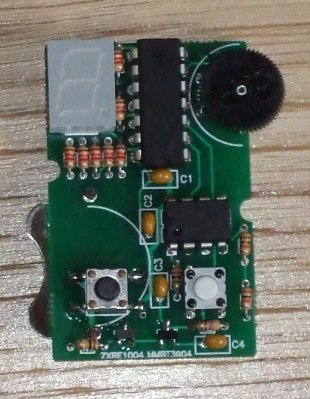
Compared to most modern inconveniences, my mRNG is simple to operate. The device has only two buttons and one thumb wheel. Orient the mRNG display side up, and with the metal ring pointed away from you (like in the picture at the top of the page and in the video below). The left button turns the device on. Hold it down to power the device. A new number is then displayed about 30 times a second — too fast for you to read. Holding the second button down stops the screen from updating so that you can read the newest random number.
The thumb wheel sets the upper bound of the random number range — 0 to that bound inclusive. The upper bound can be set as high as 15. Since the display has only one digit, the numbers are in hexadecimal (10-15 are displayed as a-f). Changing the range will cause the new upper bound to be displayed for ~.75 seconds before more random numbers are generated. When the device is powered on it will also display the current upper bound for that amount of time. It’s possible to turn the thumb wheel to be right on the border between two numbers (e.g., between 8 and 9), in which case the mRNG may keep changing the upper bound between those values. Simply turn the thumb wheel a little to move it away from the border.
Note that ‘6’ and ‘b’ (11 in hexadecimal) look similar on the display. The difference is that the top segment of the display is lit for ‘6’ but not for ‘b’. (See the exciting Wikipedia article on Seven-segment display character representations! I used the left column of characters.)
Demonstration of mRNG operation. First, the range is adjusted. Then several numbers are generated. Then the process is repeated.
Design notes
Fitting everything into a key fob meant everything had to be small. That turned out not to be a challenge in and of itself, but it meant using a coin battery, which in turn meant trying to draw 4mA or less (the current version uses 6-7mA, which is close enough). This was achieved mainly by turning off and on different parts of the circuit as needed. When it’s generating a random number, the display is off. The elements of the display itself are pulsed on and off quickly giving the illusion of being on continuously (and meaning that no more than 4 segments are ever one at one time). With that in mind, let me explain the design a bit further. (The source code and complete schematic are available below.)
Microcontroller part
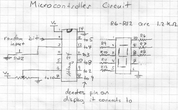
Instead of using a PIC microcontroller (like I did in my last project, or sequential logic, like in previous versions), I decided to use an AVR. Both had the right hardware features, but the PIC lacked a free C compiler for Linux and OS X. Writing assembly code was interesting, but I had better uses for my time. I chose the ATtiny24 because it had the right number of pins and an analog to digital converter.
The microcontroller drives the LEDs through 1.2kΩ resistors (that value was chosen as a good balance between high brightness and low current — other values will work). The switch doesn’t need an external pull-up resistor because the microcontroller has internal ones. No attempt is made at debouncing the switch because it isn’t necessary. The potentiometer is attached to the microcontroller’s analog to digital converter and is used to set the upper bound of the random number range.
The random bit input is connected through one of the digital input pins. Again, no attempt is made to “debounce” it — the average frequency of the random digital output was much slower than the clock speed of the microprocessor (1 MHz), so timing issues should be negligible. However this was measured for the random bit generating circuit alone, without the noise from the microcontroller. The random digital input is debiased in software using the Von Neuman method and a linear feedback shift register acting as a randomness extractor.
Random bit generating part
This circuit was inspired by Terry Ritter’s random noise sources. Diodes are often used for noise sources, but noisy low voltage diodes are hard to come by. For that reason, we use a 1.22V bandgap voltage reference (the ZXRE1004FFTA) that emulates a zener diode.
Its datasheet shows that it requires at most 8μA of current to function (4μA typical) to function, and that it is noisiest at this current (page 3). So we want to run it at close to that current, both to save power and get as much noise from it as possible. Given that the MMBT3904 transistor (datasheet) has a base to emitter voltage drop of ~.75V, the voltage reference has a drop of 1.22V, and the battery provides ~3V, that means the drop across the resistor is about 1V. So a 100kΩ resistor (R1) will let about 10μA of current through (probably a little less, since the battery’s voltage will drop).
 Given this current through the base of the transistor and the transistor having a gain of a couple 100, we expect ~2mA to flow through the collector of the transistor. We want the output from the collector to be roughly at 1.5V (in the middle of our voltage range), and a 750Ω will do that. However, any relatively close resistor value will be fine, so I’m using a 470Ω resistor (R2) which yields a drop of ~1 volt.
This signal is passed through a capacitor — so that we can have different voltage levels — and then amplified by op-amp. Because we want a digital signal, we want an “infinite” gain from the amplifier. However, we also need the average voltage level at the two inputs to be the same, so we use really big resistor (1MΩ — R3). Even the high slew rate of the OPA2340’s output isn’t enough to make this signal digital — the output didn’t hit the maximum or minimum voltage in testing. So this amplified signal is fed in the the second op-amp on the chip, and that amplifies it to digital goodness (the output is only the maximum or minimum voltage). That’s ready to feed in to the microcontroller. The output looked to have a fairly even distribution of ones and zeros, but it is debiased in the microcontroller just to be safe.
For more detail: Leon’s Mini Random Number Generator (mRNG)