Introduction
This project was the first stage of developing a controller for a radiant floor heat system. The microcontroller will use inputs from thermostats, thermocouples, a flow meter, and pressure switches to control the operation of the pumps and valves to achieve improved efficiency of the system as a whole.
This project idea came from a friend who recently built a house which utilizes an outdoor wood boiler for heating. He expressed that he was disappointed in the efficiency of the current system and wished he had more control over the system operation. This seemed like a good application of what Ive learned in this course. The main goal is to improve the efficiency of the system by shortening the amount of time that the Pumps need to run while still properly heating the home. By doing this, consumption of both electricity and wood will be reduced.
 ,
,
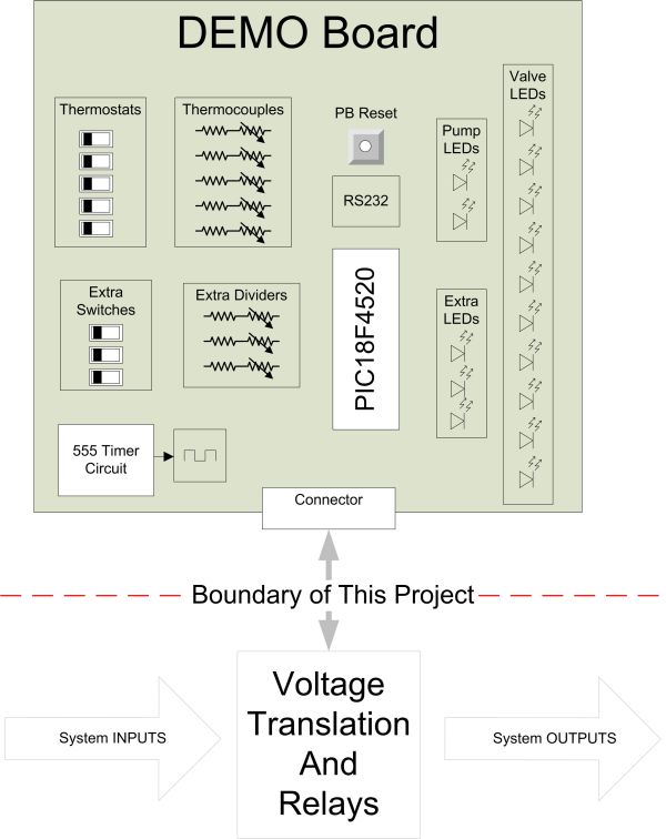
Implementation of this project involves a large amount of work outside of the microprocessor. Because of this, I bound the scope of this academic project to the control logic only. In order to implement this in the house, I will have to build the circuitry to translate the control logic over to the voltages necessary for operation of the valves, pumps and sensors. In order to verify and validate the controller logic worked as desired I built a demonstration board that models the inputs and outputs of the system. This board was used to debug the controls during development and it was also a convenient way of demonstrating this project at the end of the semester. Toggle switches were used to model the 5 thermostats, adjustable voltage dividers were used for thermocouples, a 555 Timer circuit was used for the flow meter and LEDs were used for all outputs.
High Level Design
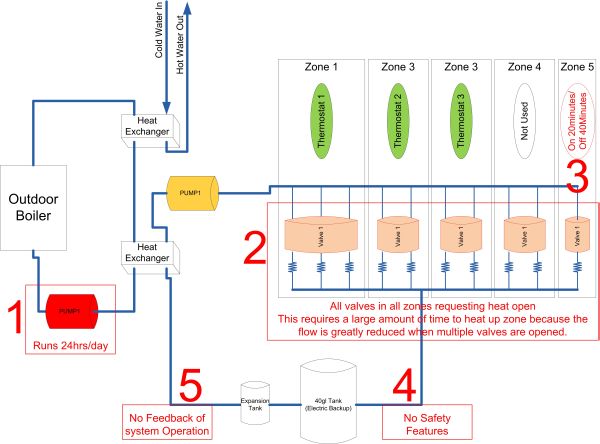
The primary goal of this project is to improve the efficiency of heating a home that utilizes radiant floor heating. Several improvements over the current system will achieve this goal. The five major upgrades are compared here with Figures 2 and 3 showing the system before and after:
- Outside Pump will be controlled based on demand for Heat and Domestic Hot water
- Old system this pump was always on
- Each Valve will be opened one at a time to maximize the flow rate to a single loop. This will decrease the time it will take to insert heat into the zone and hopefully reduce the amount of time the pumps need to run.
- Old System many valves could be opened at the same time. The more valves that were opened, the longer it would take to warm up any of the loops. Not all loops may warm up at the same rate.
- The heat exchanger in the attic will be warmed up based on current temperature and if the air handler is running (to reduce/prevent condensation).
- Old System Heat was sent to attic constantly @ 20minutes ON, then 40 minutes OFF. This ran regardless of the temperature up there or if the air handler was operating.
- A Pressure sensor and Flow meter will be added to detect if a leak or blockage has occurred. The system will be shut down if either of these conditions is detected.
- Old System there were NO such safety features.
- The system will provide real time data to the homeowner including: Pump/Valve Events, Thermocouple measurements. This data can be analyzed to make adjustments to the system operation for further improvements on its operation.
- Old System There was no feedback of the system operation.
Equations
Thermocouples The range of our ADC is 0-5v but our expected temp ranges are: 60-180degF for Hot sensors and 0-100 for the Attic sensor. Because of this we simply scaled/shifted the expected range into the ADC range. The following equations are the baseline we are starting with for development. Each of the thermocouples will be calibrated once in the real system.
BTU Calculation At each pulse of the flow meter we will read the supply tcouple and return tcouple of the heat system, get a BTU calculation and then sum all the values of BTU. At the end of the cycle for that valve send out the summation of BTU to be logged by the computer, this also allows us the resolution of which loop inside each zone draws more heat. Then in the computer side of things we can then apply a little statistics to find the highest heat demand times/loops and send a one cycle heat system demand an hour or two before the demand (forecasting).
At each pulse of the flow meter we will calculate:
Where:
W = 8.3lbs/75.3 = 0.11lbs/pulse
Since our flow meter generates 75.3 pulses per gallon
Cp = 1
∆t = (tcouplein – tcoupleout)
Logical structure
The heart of this design revolved around being able to deliver heat to specific areas of the home while running the pumps as little as possible and also not short cycling the pumps. To do this we warm up only one loop of the system at a given time. After a single valve is opened to allow hot fluid to flow through the loop, the thermocouple on the return side is monitored. Once the temperature coming out of the loop approaches the input temperature, there is little value to running more hot fluid through it. Once the loop is already warmed up it will continue to conduct heat into the floor. In other words, there is little return on investment of running the pump to move hot fluid through an already warm loop. So, we use this to decide when to transition to the next loop.
When there is active demand for heat in the home, the inside pump is kept on to prevent short cycling. Because it is kept on it was important that we ensure there are always at least one valve open while it is on. The timing diagram in Figure 5 shows how valves are activated one at time while ensuring at least one is opened while the pump is running. Also shown in this diagram (in green) once the loop is warm, a transition to the next valve begins. The temperature is unknown at the transition points when more than one valve is opened.
In addition to the inside heat control system, there is a heat exchanger which is used to supplement the Domestic Hot Water demands. It does this by preheating the cold water coming out of the well prior to it going into the Hot Water Heater. The new functionality of this controller simply monitors a thermocouple that is located near the domestic hot water heat exchanger. When that temperature drops below a threshold (indicating water is flowing from in from the well) we turn on the outside pump to heat up that exchanger.
Finally, there were two safety features added to the new system. First, a Pressure sensor was placed into the main line inside the house. This will allow detection of a leak inside the system. If a leak is detected, we immediately shut down the valves and inside pump to reduce the amount of fluid that may be lost into the walls/ceiling of the house. Second, the flow meter will be monitored to ensure water is moving and detect any blockage that may occur. One example of this occurring would be if a valve failed to open. Once we open a valve and turn on the pumps fluid should be flowing and so we should have pulses being sent in to us. If we do not see these pulses after opening a valve, then we can declare a blockage has occurred.
Hardware/software tradeoffs
The only tradeoff that was done for this project was to use the 8MHz Oscillator that is internal to the device. I have pads on the board for an external oscillator but chose not to use it. The only timing constraint we have is to process the BTU calculation each time a pulse is detected from the flow meter. The flow meter (FTB4607) puts out 75 pulses/gallon and we expect up to 8gallons/min. This means that we could have up to 600 pulses/min OR 1 pulse every 10msec. The 8MHz is plenty fast for the relatively slow operation we are performing and exact timing is not critical.
Relationship to available standards
The only standard that is applicable to this design is the RS232 serial protocol. In order to comply with this I used the built microchip USART functions and a MAX232 serial transceiver to translate the protocol out to logic levels that a PC could interpret.
Discuss existing patents, copyrights, trademarks relevant to project
There are multiple different devices for controlling heat systems. These devices are very expensive and I was not able to locate any one unit that could control the pumps, valves, and also have real time data sent to a PC interface. It would take two or three different devices to perform the controls that this microprocessor is doing. Some designs obtain control over the system by placing a pump dedicated to each zone or even each loop! Since these pumps are in the $300 range, that could get expensive very fast. The parts necessary for this controller cost less than adding one additional pump.
Industrial applications have controls similar to this design but there is nothing at a small scale for residential use. The industrial controllers typically take a room full of equipment and many thousands of dollars to implement.
Word of mouth has sparked multiple people to express interest in this low cost solution to decreasing their wood and electric consumption. So far I do not have data to show how much the actual savings will be but have many people curious of the results this will yield. Hopefully one year from now I will have that data once the system is operational in a home. At this point in time I do feel that there is a market for this type of low cost, residential controller but I dont really know how to pursue it further.
Things that were tricky
The first tricky thing that I encountered during this project was building the demo board. Because the design was very simple (3) ICs, some switches, LEDs and a hand full of discrete components I decided to etch my own board. The board layout was pretty straight forward and the chemical etching wasnt very difficult. But, after the board was etched and populated I had to debug the non functional board that resulted. Several issues were easily found using a digital multi-meter, like direct shorts and grounds. Then, to make it even more interesting, I was using all new development tools. So when I was not able to program the first test code, it was hard to tell if it was a board problem or my error using the tools. After a few frustrating days it turned out to be a bit of both.
Things that didnt worked
The first thing that didnt work was the internal pull-ups on the device. When I was drafting the board layout, I scanned the data sheet of the device to see if it supported internal pull-ups. But once I was developing the code I found that the switches that were simulating the thermostat demand were intermittent. As I pursued this further I found that the device only supported weak pull-ups on Port B and I was using switches on multiple Ports. I should have been more careful about the upfront review of the datasheet. So, it required a few extra resistors to be tacked onto the board in order to stabilize the switch values.
The other thing that didnt work very well was my insertion of vias. In an attempt to utilize a ground plane on my board I left plenty of locations for a small piece of wire to be soldered on both side to create an electrical connection between the two layers of copper. I got into trouble in a couple areas because I populated several larger footprint components (i.e. sockets) prior to soldering all of my vias into place. Because of this, I was unable to get all of the vias populated and had to resort to several soft wires routed around the board. Next time I will remember to populate all those little via wires before anything else.
Usability by you and other people
This prototype has a crude data output to a serial connection. The idea is for that data to be pulled into a PC to be analyzed. It is not very elegant but I think it gets the job done. As for modifying logic or reprogramming, this system is not usable by the general public. Currently, the only way to modify any logic is to dig into the source code and recompile then reprogram the device. This is acceptable because I intend to be the only person modifying any code so there isnt a need for an elaborate interface.
Program/Hardware Design
This phase of the project was focused on building a prototype that could control a residential heat system. The prototype had a couple of purposes: low cost/ low risk way of obtaining proof of concept and of developing the software. All of the interfaces were simulated with simple switches, potentiometers, and LEDs. The prototype board was also a convenient way to demonstrate to the professor what Ive been working on for the last month.
The software environment used for this phase of the project was MPLAB IDE v8.63 with a MCC18 compiler and a PICkit 2 programmer/debugger. All of the code written was in the c language and targeted the PIC 18F4520 microcontroller which resided on a custom PCB. The code was organized into the following main
For more detail: Heat Control System