DMM Piggyback (add RS-232)
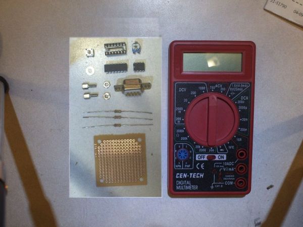
I used:
one PIC16F688
one LM358
a button and a 100k potentiometer
3 resistors (1k 10k 20k)
A PCB, piece of thin plastic, and hardware
Despite the low part count assembly and programing can be a little troublesome.
Step 1
The Theory
Since the meter is relatively cheap it has bed of nails test points (found on electronics with a “blob” IC)
These points are a circuit benders dream.
I just pulled the input to the original chip (I will call the golden pin) amped it, ran it through the PIC, and sent it through serial. I also used a potentiometer to encode the selector dial.
The golden pin is the middle pin of the left side (circled in red)
DO NOT SOLDER TO THE LARGE PAD EVEN THOUGH ITS CONNECTED TO THE PIN THOUGH A CAPACITOR
Step 2
The Circuit
The op amp is set up as 11x voltage amp from the golden pin. I used an amp because the pin only gives 200mV on full DC voltage signal. The amp feeds AN0 of the pic. The pot goes to AN7 no amp needed and hooks to the same power as the PIC and OP AMP
USE ONLY LM358 OR EQUIVALENT. LM741 DOES NOT WORK!
Step 3
The Dial Encoder
To mount it cut a thin plastic sheet (like the DMM’s container) to fit to the screw holes.
then cut a hole for the pot (make it a tight fit) I also cut a hole for the diode, lead board solder, and power leads
take out the screws slip the pot in the plastic and screw it down.(I pre drilled screw holes)
I used a screw and cut the head flat(see last pic keep green part) to couple the dial and pot together.
The screw fits nice in the hollow center of the dial.
The flat head goes into the flat-head screw hole on the pot.
I suggest using red lock tight because if the screw losens the encoder stops working.


