Three weeks before the Houston Maker Faire Chris came to me asking if we could whip up a low cost giveaway for the faire. I wanted to giveaway something more than a blinky LED badge since that is the typical electronic swag at Maker Faire. It had to be something that the person would wear and would want to show off to other Makers to spread the word about MacroFab. Blinking LEDs are always necessary though. The budget was set to under $3 a unit and I was given only three weeks to prototype, design, and manufacture the giveaway.
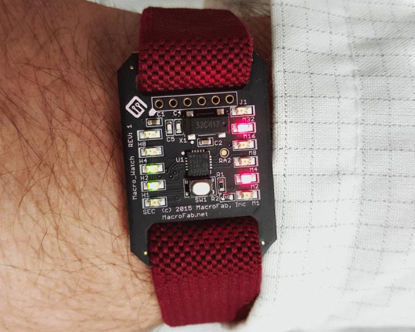
The Macro Watch stemmed from those constraints. I picked the PIC16F527 microcontroller by Microchip to be the core of the watch because it was the cheapest MCU I could find that had enough I/O and I knew at least a little bit about it in terms of writing code for and programming. The watch shows time in binary since doing so requires less LEDs to display time than the usual watch patterns, driving the cost down. The least expensive SMD 32.786KHz crystal on Mouser (part # ABS25-32.768KHZ-T) was used to make the PIC16F527 run in “LP” mode (Low Power Crystal Mode) and help increase the accuracy of the time keeping without blowing through the battery quickly. MacroFab House Parts were used to fill in the rest of the passives and switches. For the wrist strap I ordered ESD wrist straps from China in bulk.
The plan was to spend 1 week prototyping and designing the board, 1 week for parts to arrive, and 1 week for assembly and packaging. An aggressive schedule on the R&D side but doable. What could possibly go wrong?
Stephen had an old PICDEM Lab prototyping breadboard so I ordered some PIC16F527-E/P components which are the DIP version of the microcontroller I was planing to use. A couple days later I popped it into the PICDEM Lab bread board, plugged in a PICkit 3 programmer and was talking to the PIC16F527 right away. Unfortunately, that was where the luck ran out.
First was to get an LED to blink. Easy no? I plugged an LED in the RA0 port and wrote a small blinky program. LED did not blink. I was not very familiar with this chip and figured it had to be some kind of configuration issue. A couple hours later, after triple checking my hardware and code, I came across table 6-1 “PORTA PINS ORDER OF PRECEDENCE” which lists the priority of how the configuration registers use the pins. I knew about setting the ANSEL registry to 0x00 but there was “C1IN+” listed on RA0. This PIC had comparators that where enabled by default! The register CM1CON0 had to be set to 0x00 as well before RA0 could be used as a digital GPIO. Finally success! Blinking LEDS!
For more detail: Designing and Building the Macro Watch