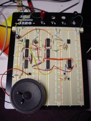
I completed a 2-part assignment for this week. The first part was to build a sorta-random sound generator based on a schematic that Joe Paradiso made available. The second part was to build a circuit that could transmit MIDI messages – this will go towards my final project.
Sound generator
The description for this assignment is here.
Electronics knowledge base from 2001 can be found here.
Midi Output
Midi output (and probably input) is going to be important to my final project. For this reason I’ve decided that one important step between now and completing my final project is to learn how to emit (and receive) MIDI messages from a PIC. I’ve found several resources online that give directions on how this can be done. Here are several of the more useful ones:
MIDI is basically serial data transmitted at 31,250 baud (bits-per-second) through a circuit with a resistance of about 660 ohms. Parity must be set to NONE, the number of stop bits must be set to 1 and finally the number of data-bits must be set to 8. The baud rate MIDI uses means that during transmission each bit should last for 32 micro-seconds. MIDI is transmitted in chunks of 3 bytes (each byte is 8 bits) and each transmitted byte is padded with a start bit (0) before it and a stop bit (1) after it. The three bytes of the typical MIDI message consist of one status byte and 2 data bytes (in that order). There is a lot of information online about what makes up valid status/data bytes. The bits in each byte are transmitted Least-Significant-Byte (LSB) first.
So if I wanted to transmit the number 144 (this is the code for a NOTE-ON in MIDI), the bit-pattern would be:
what I want to tranmit: 10010000
what bits get put on the line (read left-to-right): 0 00001001 1
(note: the spaces are just to show that there is a start and stop bit)
I was doing some testing while I developed my circuit, and I was sending the following bytes down the MIDI line: 144 144 144
This sequence caused me a lot of headache, because I didn’t realize for the longest time that IT’S NOT VALID MIDI. It’s three control bytes in a row and no data bytes. So even when I had the hardward constructed correctly, the computer was still not registering any MIDI messages coming through. Be careful of that.
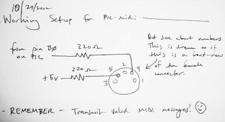
Read my notes from this testing session here (note that in Hexidecimal format, 144 is 0x90)
Since MIDI is really just serial data, it’s pretty easy (in theory) to transmit it, since many microcontroller development languages have routines for transmitting and receiving serial built-in. The signaling in MIDI is based on current rather than voltage though, which means that in order to transmit a message, you have to have a certain amount of current flowing through the circuit. For longer MIDI cables, you’ll need more current pushing through the circuit.
Resting state on the line is when no current is flowing. This is actually a logical 1. So I think about it like this:
- Want to transmit a 1 -> no current flows
- Want to transmit a 0 -> flow that current!
For more detail: Circuit design and electronics