


Summary of Wireless 10 channel receiver using PIC16F630
This article describes a wireless receiver project using a PIC16F630 microcontroller to control 10 outputs via an RC5 protocol TV remote. Users can switch between systems (e.g., TV, SAT) and program unused remote buttons to activate specific channels by holding a button while powering the device on. The system validates incoming IR codes against stored EEPROM data to execute commands, with LED indicators showing status.Parts used in the Wireless 10 Channel Receiver:
- PIC16F630 microcontroller
- TV remote control with RC5 protocol
- EEPROM for storing system codes
- LED indicator
- Power supply
- 74HC595 shift register (optional for expansion)
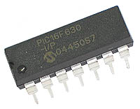
Use it as follows:
When 'TV' mode is selected on your remote-control, you can with the buttons 0 through 9 on it, steer 10 outputs on and off.
When there is an unused system on your remote-control (SAT, AMP, DCC, VCR2) then the code in the PIC can be changed with the remote-control to another system.
This goes as follows:
Switch the power from the PIC to OFF.
Select an unused system on the remote-control (like SAT, AMP, DCC or VCR2).
Push a button (0-9) on the remote-control and keep it pressed while switching the power from the PICmicro ON.
If the LED blinks a couple of times slow, then the new system is programmed in EEPROM.
Now the buttons 0-9 works only when the remote-control stands in the just programmed system mode.
The LED burns continue while a valid button from a valid system is received and blinks fast when an invalid IR-code is received.
'System' means equipment like TV, VCR, TAPE, SAT, etc.
'Command' means buttons on the remote like 0-9, I/II, PLAY, STOP, etc.
A push on a button from the RC5 remote-control sends: a header, a togglebit, an extended (7th) command bit, a 5 bit system-code and a 6 bit command code.
When the received system-code is equal to the programmed one in the EEPROM from the PIC, then the command-code is executed.
The programs are based on the 14-pins 16F630, but they can ofcourse make workable for almost every type PIC.
To see what system- and command-code's your remote-control sends, you can build an other (easy) project: RC5/RC6 codes on a LC-Display
That project displays the IR-code's on LCD so this project can be extend to steer much more channels wireless (till 127 outputs!) with for example the 74HC595.
For more detail: Wireless 10 channel receiver using PIC16F630
- How many outputs can this project steer?
The project can steer 10 different things wirelessly. - What protocol does the remote control use?
The system uses the RC5 protocol from manufacturers like Philips, Grundig, and Marantz. - Can I change the number of channels?
Yes, if the Proton PIC Basic compiler is available, you can change the number of channels. - How do I program a new system mode?
Switch power off, select an unused system on the remote, push a 0-9 button while turning power on until the LED blinks slowly. - When do the buttons work after programming?
The buttons 0 through 9 work only when the remote-control stands in the just programmed system mode. - What does a fast blinking LED indicate?
A fast blink indicates that an invalid IR-code has been received. - What components make up an RC5 signal?
An RC5 signal consists of a header, togglebit, extended command bit, 5-bit system-code, and 6-bit command code. - How can I extend the project to steer more channels?
You can extend it to steer up to 127 outputs by using a 74HC595 shift register.
Related projects
Infra/radio remote control transmitter/receiver with PIC16F630
description This is a general purpose remote control project with using programmable PIC microcontrollers. Schematics are shown for using infrared (RF) or...
Home Automation & Security · PIC12F629IR REMOTE CONTROL CIRCUITS WITH PICMICRO
PIC12F629, PIC16F630, PIC16F84 microcontroller prepared with different control circuits available 3-8-10 Channel Control projects have hex and asm code only 10 channels...
Home Automation & Security · PIC16F6308 Channel IR Remote Control
This IR remote control that you can use to control other devices or circuits up to 8 devices. The control codes are...
Communication & Interfacing · PIC18F4520CAN FD Node based on a PIC18 Microcontroller
The introduction sets the stage for an embedded systems project that involves developing a Embedded C CAN FD project using the MCP2517FD...
Communication & InterfacingLAN9662 Gigabit Switch: Optimized for Industrial Ethernet
Introduction It should come as little surprise therefore that one element of what is now more commonly referred to in some circles...
Communication & InterfacingPIC Microcontroller: Fundamentals & Applications for Students
Introduction Microcontrollers are the key components in the embedded systems market. A variety of embedded systems was formed and developed after the...

Ibrar Ayyub
I am an experienced technical writer holding a Master's degree in computer science from BZU Multan, Pakistan University. With a background spanning various industries, particularly in home automation and engineering, I have honed my skills in crafting clear and concise content. Proficient in leveraging infographics and diagrams, I strive to simplify complex concepts for readers. My strength lies in thorough...