
Summary of Water Wave/Tide/Level Meter 2.0 using PIC16F88
This article details the construction of a capacitance probe for measuring water levels in non-distilled water. It describes using insulated wire as a dielectric, with specific recommendations for PTFE or enamelled copper wire to ensure durability and sensitivity. The design accommodates both short probes and long probes using a U-shaped loop to avoid sealing issues and double capacitance. The electronics unit utilizes a 555 timer monostable circuit and an LM324 op-amp to convert pulse width into a proportional voltage, requiring careful waterproofing and grounding to prevent corrosion.
Parts used in Capacitance Probe:
- Insulated wire (PTFE or enamelled copper)
- PVC plastic coated multistrand hookup wire
- Single wire with sliding clamp
- Metal frame
- Light springs
- Plastic pulley
- Waterproof box
- Output cable
- Epoxy and heatshrink tube
- Grommet
- Coaxial cable
- 555 timer IC (LM555, NE555, or ICM7555)
- Resistor R7 and Capacitor C5
- Differential stage IC1B (LM324 quad op-amp)
- 3-terminal voltage regulator (LM7808, LM7812, LM7815, etc.)
- Micropower regulator (MAX666)
Capacitance Probe
A simple probe can be made using insulated wire. The insulation is then the dielectric of an cylindrical capacitor with the inner conductor as one plate and the water as the other.
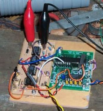
The probe is not suitable for distilled or very pure water because it is not conductive enough. It works well even in relatively clean water such as roof runoff water in a plastic tank. PVC plastic coated multistrand hookup wire will work but is porous and may eventually give trouble. Better to use the PTFE (teflon) equivalent. Enamelled copper wire gives a high capacitance per unit length because the insulation is very thin and this is suitable for short probes of up to about 200mm.
For long probes a pipe with a sliding clamp to tension a single wire works well. Keep the wire away from the pipe to avoid turbulence effects. The problem with a single wire is sealing the end under water, especially the PTFE type. It may be possible to melt-seal the end but it is easier and more reliable to make a loop to form a U shape so that both ends are out of the water, connecting one or both ends to the electronics, with the metal frame being the other connection to the electronics common and to the water. A benefit is that the capacitance per unit length is doubled but in the case where the probe is being used to measure wave height it must be aligned so that both arms of the wire are normal to the wave, otherwise an error could result.
Light springs can be used at the top to maintain wire tension. Make sure there are no sharp edges at the bottom of the U where the wire is held to the frame. A plastic pulley gives a smooth turn. The probe needs to be attached to something fixed like the side or top of a water tank, or to a pier. If the water depth is not too great a stake can be driven into the bottom of a river or dam and the probe attached to it (which also provides a good grounding point). The electronics should be above water in a waterproof box that is attached to the metal probe frame. The box cannot be separated some distance away from the probe because the capacitance of a cable would be too great compared to the probe capacitance. The output cable can also bring low voltage unregulated DC power to the unit. It can be long and even be under water back to dry land if required.
Corrosion will be a problem, even with freshwater such as a rainwater tank. Make sure all external joins are soldered then coated in epoxy and heatshrink tube. If possible run the PTFE wire via a grommet into the sensor electronics unit as nothing sticks to teflon. The original prototype was mounted a meter from the tank being measured, and the signal was delivered to the PCB using a piece of coax thorugh a grommet. Water wicked along inside the coax and corroded the copper inside the cable. The DC bias provided by the oscillator will make things worse.
Electronics Units
Analog Electronics Unit
Here’s an analog water level meter that uses commonly available parts. The output is a voltage that is proportional to the water level:
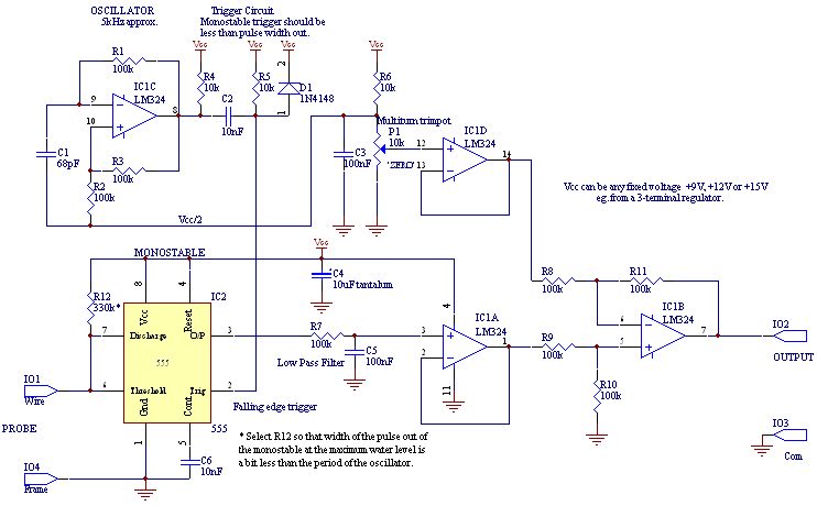
The monostable is a 555, eg. LM555 or NE555, or could be a ICM7555, the CMOS version of the 555 for lower power consumption. The width of the pulses out of the 555 is proportional to the water level. R7 and C5 form a low pass filter to smooth the DC value of the pulse train. Their values can be increased to lower the cutoff frequency if dynamic response is not required. The lower the cutoff frequency the more noise immunity the device will have.
The zero offset is removed in the differential stage IC1B. The LM324 is a quad op. amp. that can be used in single supply configuration. The maximum output of an LM324 is about 1.5V less than the supply voltage Vcc. The supply can be from a 3-terminal regulator eg LM7808,LM7812, LM7815 – or LM78L08, LM78L12 or LM78L15. The voltage input to one of these regulators needs to be about 2V higher than the regulated voltage. For low power applications a micropower regulator like the MAX666 could be used.
For more detail: Water Wave/Tide/Level Meter 2.0 using PIC16F88
-
Can this probe work with distilled water?
No, the probe is not suitable for distilled or very pure water because it is not conductive enough. -
What type of wire is best for short probes up to 200mm?
Enamelled copper wire is suitable for short probes because its thin insulation provides high capacitance per unit length. -
How can you seal the end of a long single wire probe underwater?
It is easier and more reliable to make a loop to form a U shape so that both ends remain out of the water. -
Why must the probe be aligned normal to the wave if measuring wave height?
If not aligned correctly, an error could result because the probe measures the interaction between both arms of the wire. -
Can the electronics box be placed far away from the probe?
No, the box cannot be separated by some distance because the capacitance of a long cable would be too great compared to the probe capacitance. -
How should external joins be protected against corrosion?
All external joins should be soldered then coated in epoxy and heatshrink tube. -
What component forms the low pass filter in the analog electronics unit?
Resistor R7 and Capacitor C5 form a low pass filter to smooth the DC value of the pulse train. -
Does the output voltage change based on water level?
Yes, the output is a voltage that is proportional to the water level, where the pulse width from the 555 is proportional to the level.
