Summary of Water Level Indicator and Controller using PIC Microcontroller
This project utilizes a PIC16F877A microcontroller to wirelessly monitor and control water tank levels. It features a sensing section with an HT12E encoder and ASK RF transmitter, paired with a receiver using an HT12D decoder. The system automatically starts the motor when water is low and stops it when full, while displaying status on an LCD and indicating levels via LEDs and a buzzer.
Parts used in the Water Level Indicator Controller:
- PIC16F877A Microcontroller
- HT12E Encoder
- HT12D Decoder
- ASK RF Transmitter Module
- ASK RF Receiver Module
- LCD Display
- Motor
- Buzzer
- LED Bar Indicators
- Push Button Switch
- 9V Battery
- Power Supply (5V and 12V)
Here is a simple, versatile project which indicates the level of water and automatically controls it by using PIC Microcontroller. The Water Level Sensing Section senses the level of water in the tank and sends it (wireless) to the Receiver Section. Receiver Section is connected to the Controlling Section, which process the received information and produces visual, sound indications and controls the operation of the motor whenever required. The project is divide into 4 sections.
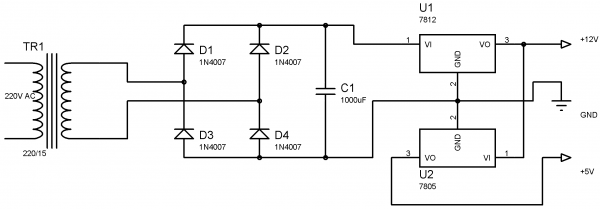
1. Power Supply Section
Power Supply section provides required supply for Receiver and Controlling modules. Receiver module requires +5V power supply. Controller module requires +5v and +12v supply. Circuit Diagram:
2.Water Level Sensing Section
Level Sensor module is made of with HT12E encoder and ASK (Amplitude Shift Keying) RF transmitter. This circuit can be drive using 9V battery. For more details about this transmitter, please read the article Wireless RF Transmitter and Receiver using ASK RF Module. This circuit is placed near the Water Tank and connected to the tank as show in the figure below.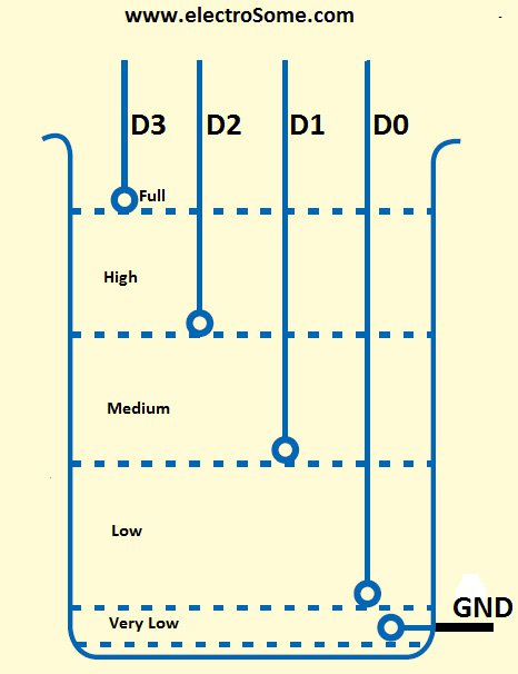
3. Receiver Section

Receiver Module is made of with HT12D decoder and ASK RF receiver. The data transmitted by the Sensor module is received by this module and is given to the Controlling Module. For more details about this receiver, please read the article Wireless RF Transmitter and Receiver using ASK RF Module.
4. Controlling Section
Circuit Diagram
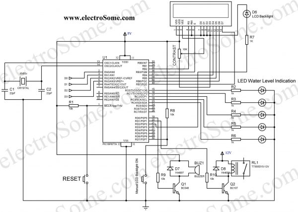
The soul of the Controlling Section is PIC16F877A. It process the data given by the Receiver Section. LCD Display, LED Indications and Motor status are updated according to the data. You can download the hex file and mikroC Source Code at the bottom of this article.
MikroC Code
// LCD module connections
sbit LCD_RS at RB2_bit;
sbit LCD_EN at RB3_bit;
sbit LCD_D4 at RB4_bit;
sbit LCD_D5 at RB5_bit;
sbit LCD_D6 at RB6_bit;
sbit LCD_D7 at RB7_bit;

sbit LCD_RS_Direction at TRISB2_bit;
sbit LCD_EN_Direction at TRISB3_bit;
sbit LCD_D4_Direction at TRISB4_bit;
sbit LCD_D5_Direction at TRISB5_bit;
sbit LCD_D6_Direction at TRISB6_bit;
sbit LCD_D7_Direction at TRISB7_bit;
// End LCD module connections

char txt1[] = "Water";
char txt2[] = "Level";
char txt3[] = "Indicator";
char txt4[] = "And Controller";

char mtr1[] = "Motor ";
char mtr2[] = "OFF";
char mtr3[] = "ON";

char wtr1[] = "Level: ";
char wtr2[] = "Very Low";
char wtr3[] = "Low";
char wtr4[] = "Medium";
char wtr5[] = "High";
char wtr6[] = "Full";

void main()
{

  int i = 0;
  int c = 16;
  int b = 0;
  CMCON = 0x07;
  ADCON1 = 0x06;
  TRISA = 0x0F;                  // set direction to be input
  PORTA = 0x00;
  PORTD = 0x00;
  PORTC = 0x00;
  TRISB = 0x00;                  //  set direction to be output
  TRISC = 0x00;                  // set direction to be output
  TRISD = 0x80;                  // set direction to be output

  PORTD.F2 = 1;
  PORTD.F7 = 1;

  Lcd_Init();                    // Initialize LCD
  Lcd_Cmd(_LCD_CLEAR);           // Clear display
  Lcd_Cmd(_LCD_CURSOR_OFF);      // Cursor off
  Lcd_Out(1,1,txt1);             // Write text in first row
  Lcd_Out(2,1,txt2);             // Write text in second row
  Delay_ms(500);
  Lcd_Cmd(_LCD_CLEAR);           // Clear display
  Lcd_Out(1,1,txt3);             // Write text in first row
  Lcd_Out(2,1,txt4);             // Write text in second row
  Delay_ms(500);

  // Moving text
  for(i=0; i<15; i++)
  {
    Lcd_Cmd(_LCD_SHIFT_RIGHT);
    Delay_ms(125);
  }

  i=0; //Motor Status OFF

  do
  {
    Lcd_Cmd(_LCD_CLEAR);
    Lcd_Out(1,1,wtr1);
    Lcd_Out(2,1,mtr1);
    if(c>0)
    {
      PORTD.F2 = 1               //LCD Backlight ON
      c--;
    }
    else
      PORTD.F2 = 0;              //LCD Backlight OFF

    if(b>0)
    {
      PORTD.F0 = 1;              //Buzzer ON
      Delay_ms(125);
      PORTD.F0 = 0;              //Buzzer OFF
      b--;
    }

    if(PORTD.F7 == 0)            //Manual Backlight ON
      c = 16;

    if(PORTA == 0x0F)
    {
       PORTD.F1 = 1;
       Lcd_Out(1,8,wtr2);
       Lcd_Out(2,7,mtr3);
       PORTC = 1;
       if(i == 0)
       {
          c = 16;                //Backlight
          b=3;                   //Buzzer
       }
       i=1;
    }
    else if(PORTA == 0x0E)
    {
       Lcd_Out(1,8,wtr3);
       if(i == 1)
          Lcd_Out(2,7,mtr3);
       else
          Lcd_Out(2,7,mtr2);
       PORTC = 3;                 //LED Bar
    }
    else if(PORTA == 0x0C)
    {
       Lcd_Out(1,8,wtr4);
       if(i == 1)
          Lcd_Out(2,7,mtr3);
       else
          Lcd_Out(2,7,mtr2);
       PORTC = 7;                  //LED Bar
    }
    else if(PORTA == 0x08)
    {
       Lcd_Out(1,8,wtr5);
       if(i == 1)
          Lcd_Out(2,7,mtr3);
       else
          Lcd_Out(2,7,mtr2);
          PORTC = 15;              //LED Bar
    }
    else if(PORTA == 0x00)
    {
       Lcd_Out(1,8,wtr6);
       Lcd_Out(2,7,mtr2);
       PORTD.F1 = 0;              // Motor OFF
       if(i == 1)
       {
         c = 16;                  //Backlight
         b = 3;                   //Buzzer
       }
       i=0;                       //Motor Status Updated
       PORTC = 31;                //LED Bar
    }
    else
       PORTA = 0x0F;
   Delay_ms(125);


  }while(1);                     // Endless loop
}
Working
For the transmission and reception of data we have used Holtek encoder-decoder pair of HT12E and HT12D. Both of them are CMOS ICs working voltage ranges from 2.4 to 12v. The oscillator resistances are chosen according to the datasheet. When water level raises, the data pins of the encoder will be grounded corresponding to the level of water, which will be transmitted to the Receiver via ASK RF module. The received data is decoded by the decoder HT12D. LED on the receiver indicates that it is receiving data. Then the data is given to the PIC for processing.
| D0 | D1 | D2 | D3 | Status |
|---|---|---|---|---|
| 0 | 0 | 0 | 0 | All data pins are grounded, indicates tank is Full. |
| 0 | 0 | 0 | 1 | Water level is below D3 and above D2, indicates High level. |
| 0 | 0 | 1 | 1 | Water level is below D2 and above D1, indicates Medium level. |
| 0 | 1 | 1 | 1 | Water level is below D1 and above D0, indicates Low level. |
| 1 | 1 | 1 | 1 | Water level is below D0, indicates Very Low level. |
When the water level becomes Very Low, the motor will turned ON, buzzer sounds and the LCD backlight will automatically turned ON for 5 seconds. After this, when the water level reaches Full level, the motor will automatically turned OFF, buzzer sounds and the LCD backlight will automatically turned ON for 5 seconds. During normal operation you can manually turn on LCD backlight by pressing the Push button switch. The LCD indicates the Level of water (‘Very Low’, ‘Low’, ‘Medium’, ‘High’,’Full’) and the status of the motor (‘ON’ or ‘OFF’). The LED bar will also indicate the level of water.
Download Here
You can download the hex file, mikroC source code, PCB Design, Layout, Proteus and Orcad files here.
Source : Water Level Indicator and Controller using PIC Microcontroller
- How does the system transmit water level data?
The sensing section uses an HT12E encoder and ASK RF transmitter to send data wirelessly to the receiver. - What microcontroller is used as the core of the controlling section?
The PIC16F877A microcontroller processes the received data and controls the system operations. - Can the LCD backlight be manually turned on?
Yes, you can manually turn on the LCD backlight by pressing the Push button switch during normal operation. - What happens when the water level reaches Very Low?
The motor turns ON, the buzzer sounds, and the LCD backlight automatically turns ON for 5 seconds. - How does the system know when to stop the motor?
When the water level reaches Full, the motor automatically turns OFF, the buzzer sounds, and the backlight activates for 5 seconds. - What components are used for wireless communication?
The project uses an ASK RF transmitter and receiver module along with HT12E and HT12D ICs. - Does the LED bar indicate the water level?
Yes, the LED bar indicates the specific level of water alongside the LCD display. - What voltage supply does the controller module require?
The controller module requires both +5V and +12V power supply.