
As a fan of taking my dihydrogen monoxide in straight, uncut, uncorrupted liquid form, I purchased a six stage reverse osmosis filter some years ago.
My filter is a few years old now, and the super calcium enriched water we have in Michigan has taken its toll. The filter used to shut off when the production tank was full. However, the filter has recently developed a leak in the auto shutoff valve, so it’s constantly consuming water, even if the pressure tank can’t hold any more. This leak started slow, and I could live with it. In a few months, it had sped up to wasting a considerable amount of water. So, rather than replace the auto shutoff valve, which would have been too easy, I decided to add a microcontroller instead. The other problem my filter has, I discharge the brine water out to storage tanks next to my house, which hold the waste water, for watering plants and other uses. Problem is, when the temperature gets too low, the discharge line can freeze, which is very bad for the filter. So my microcontroller solves this problem as well.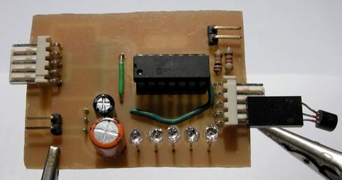
The mcu is performing a few simple logic operations, with a few twists. First, it checks to see if the pressure tank reads “high” or “low”, via a pressure sensitive switch. If the tank reads “low”, that is the first “1″ in my logic comparison – a simple AND operation. Second, the mcu checks to see if the outdoor ambient is above 38°F. That is my second “1″ in the AND operation. If the pressure is low and the temp is good, a flag is set to enable the boost pump and water supply valve. A timer detects this flag and begins a countdown of 30 seconds (roughly). I chose to use a timer to buffer any false readings that may occur for whatever reason. After the 30 seconds has elapsed, the mcu turns on two mosfet switches, controlling the current for a solenoid valve and the boost pump. The mcu continues to monitor the two variables of the AND operation, if either changes, the “make water” flag is cleared, and the mcu turns off the water supply valve and the boost pump.
Two N-Channel mosfets control the current for the boost pump and the solenoid valve. The valve is a 24VAC lawn sprinkler valve, but I have tested it and it works well on 12vdc. The boost pump is a 100 gpd, 100 psi diaphragm pump, which delivers slow but steady high pressure water for optimal membrane operation. Pull-down resistors R3 and R7 are provided to prevent mosfet self-destruction should something happen to the microcontroller. The connectors TEMP, PRES and DISABLE are pin headers for connecting to external transducers. For reading temperatures, I chose the Dallas DS18B20 high precision digital thermometer with 1-Wire interface. The pressure switch is a simple normally closed pressure sensitive switch that opens around 45 psi. It is wired to present the PIC with a logical “1″ when the pressure is low. The disable connector will be connected to a shut-off switch, allowing me to temporarily halt production. The LEDs are just for indication of various operational conditions and modes. A 7805 regulator provides the pic with 5v from the 12v supply for the pump and valve.
Rather than cobble this together on protoboard, I made up some PCBs real quick. Here is a top view of the controller, without any connections, except for the thermometer. When installed, the thermometer will be installed at the end of a ~10ft shielded cable, for sensing the ambient temperature near my water storage tanks.
Here is the messy solder side of my controller. I haven’t hosed it down with alcohol yet to clean off the flux. I waited till it was good and late before soldering anything, so some of those joints are pretty nasty – I apologize.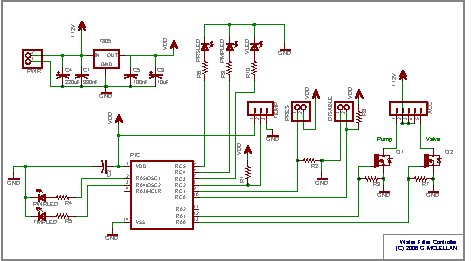
The PCB layout was pretty easy – I had a lot of room to work with, as the enclosure I have selected is pretty big. This image shows the parts layout, along with the bottom copper artwork. The top layer artwork (in red) is for two jumper wires. Clicking on the above layout will get you a 300 DPI monochrome TIFF of the bottom layer artwork. Print this out at 300DPI and you should have a 1:1 scale of the pcb, incase anyone wants to make their own. Hit the contact justDIY link on the side menu if you want the firmware source code – it is written in Proton Plus basic.
For more detail: Water Filter Controller
