Most of microcontrollers work within 5 volt environment and the I/O port can only handle current up to 20mA; therefore if we want to attach the microcontroller’s I/O port to different voltage level circuit or to drive devices with more than 20mA; we need to use the interface circuit. One of the popular method is to use the Bipolar Junction Transistor (BJT) or we just called it transistor in this tutorial. I have to make clear on this BJT type to differentiate among the other types of transistors family such as FET (Field Effect Transistor), MOSFET (Metal Oxide Semiconductor FET), VMOS (Vertical MOSFET) and UJT (Uni-Junction Transistor).
A. The Switch
The transistor actually works as a current gainer; any current applied to the base terminal will be multiplied by the current gain factor of the transistor which known as hFE. Therefore transistor can be used as amplifier; any small signal (very small current) applied to the base terminal will be amplified by the factor of hFE and reflected as a collector current on the collector terminal side.
All the transistors have three state of operation:
- Off state: in this state there is no base current applied or IB = 0.
- On active state: in this state any changes in IB will cause changes in IC as well or IC = IB x hFE. This type of state is suitable when we use transistor as a signal amplifier because transistor is said is in the linear state. For example if we have a transistor with gain of 100 and we increase the IB from 10uA to 100uA; this will cause the IC to swing from 1000uA to 10000uA (1 mA to 10 mA).
- On saturate state: in this state any changes in IB will not cause changes in IC anymore (not linear) or we could say IC is nearly constant. We never use this state to run the transistor as a signal amplifier (class A amplifier) because the output signal will be clamped when the transistor is saturate. This is the type of state that we are looking for on this tutorial.
From the picture above we could see the voltage and current condition of transistor on each state; if you notice when transistor is in off state the voltage across collector and emitter terminal is equal to the supplied voltage, this is equivalent to the open circuit and when transistor is in saturate state the collector to emitter voltage is equal or less then 0.2 Volt which is equivalent to the close circuit. Therefore to use transistor as a switch we have to make transistor OFF which equivalent to the logical “0” and SATURATE which is equivalent to the logical “1“.
One of the famous diagrams that show the transistor operating state is called the transistor static characteristic curve as shown on this following picture:
When we operate transistor as the class A common emitter amplifier usually we choose to bias the transistor (apply voltage on VBE and VCE) in such a way (Q-Point) that IC and VCE (output) will swing to its maximum or minimum value without any distortion (swing into the saturation or cut-off region) when the IB (input) swing to its maximum or minimum value; but when we operate the transistor as switch we intentionally push the transistor into its saturation region to get the lowest possible VCE (i.e. near 0.2 volt) when we need to make the transistor ON (switch ON) and into its cut-off region when we need to make the transistor OFF (switch OFF).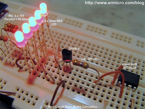
The above diagram show a typical microcontroller interface circuit using NPN transistor; the RB resistor is used to control the current on base terminal that make transistor OFF and ON (saturate); while the RC resistor is the current limiter for the load. if the load operate with the same voltage as the supplied power (Vcc) you can by pass the RC (not use).
Notice the diode (also known as the clamp diode) in the inductive load circuit is needed to protect the transistor again the EMF (Electromotive Force) voltage generated by the inductor component when the transistor is switched on and off rapidly, this voltage is oppose the source voltage. The diode will act as a short circuit to the high voltage generated by the inductor component, you can use any general purpose diode with capable on handling minimum 1 A of current such as 1N4001, 1N4002, etc.
On the picture shown above you could see how we connect the transistor as the high active switch (logical high) also known as low side switch using NPN transistor and the low active switch (logical low) also known as high side switch using PNP transistor.
Ok let’s calculate each of the RB and RC value on this following NPN transistor circuit:
On the circuit above we are going to use 2N3904 (the cheap general purpose transistor where you could easily found on your local market) to drive 5 LED from microcontroller port, from the 2N3904 datasheet we get this following information:
IC max = 200mA (this is maximum value that will make your transistor smoked, in practical application always use just half of the maximum value mentioned on the datasheet), hFE = 100 to 300, VBE saturate = 0.65 Volt, VCE saturate = 0.2 Volt
For most transistor in general we can use VBE = 0.7 Volt (should be saturate) and VCE = 0 Volt. Using the 5 volt power supply (VCC) and assuming VLED = 2 Volt, with each of them consuming 15 mA, we could calculate the RC value using the Ohm’s law as follow:
IC = 5 x 15 mA = 75mA (0.075 A), this current is still far bellow the maximum IC allowed by 2N3904 transistor.
RC = (VCC – VLED) / IC = (5 – 2) / 0.075 = 40 Ohm
Power Dissipation on the RC resistor will be
P = (VCC – VLED) x IC = (5 – 2) x 0.075 = 0.225 Watt
Base on the above calculation we could use the nearest higher value available on the market; which is 47 Ohm, 0.5 watt resistor (for heat dissipation usually we use twice of the watt value calculated).
Assuming the hFE minimum is 100; the minimum current required in the transistor’s base terminal to drive the LED is:
IC = hFE x IB
IB = IC / hFE = 0.075 / 100 = 0.00075 A (0.75 mA)
This current can easily be supplied by most microcontroller I/O port; which is capable to drive up to 20 mA output current. Again by applying the Ohm’s law we could calculate the RB value as follow:
RB = (VPORT – VBE) / IB
Assuming the minimum average voltage of microcontroller I/O port (VPORT) with logical “1” is about 4.2 volt (the microcontroller is powered by 5 volt supply):
RB = (4.2 – 0.7) / 0.00075 = 4666.66 Ohm
Power dissipation on the RC resistor will be
P = (VPORT – VBE) x IB = (4.2 – 0.7) x 0.00075 = 0.002625 Watt
Base on the result you could use 4K7 Ohm, 0.25 Watt resistor (this is the common resistor which you could easily found on the local market i.e. 0.25 watt and 0.5 watt).
Use this RB calculation as your maximum reference value; in the real world most of the transistors hFE is vary and being measured (tested) with different VCE and IC value not to mention different specification even though you use the same transistor type. Therefore the real RB value could be lower than 4K7 if you really want to drive the transistor into its fully saturate mode where the VCE near 0.2 volt.
Now the question is how we determine the exact value? To answer to this question I build this following testing circuit base on the RC and RB calculated value above using the Atmel AVR ATTiny25 microcontroller to blink the five LED:
Note: the reason I used RC = 3×150 Ohm because at that time I run out the required 47 Ohm resistor, therefore you could use just single 47 Ohm resistor or if you only have 150 Ohm as I did, you could use them as I did.
Bellow is the C Program that I used to test this circuit:
//***************************************************************************
//  File Name	  : trswitch.c
//  Version	  : 1.0
//  Description   : Transistor as Switch: Simple LED Blinker
//  Author  	  : RWB
//  Target  	  : Atmel AVR ATTiny25 Microcontroller
//  Compiler      : AVR-GCC 4.3.0; avr-libc 1.6.2 (WinAVR 20090313)
//  IDE           : Atmel AVR Studio 4.17
//  Programmer    : Atmel AVRISPmkII
//  Last Updated  : 1 November 2009
//***************************************************************************
#include <avr/io.h>
#include <util/delay.h>
int main(void)
{
   // Initial I/O
   DDRB |= (1<<PB3);       // Set PB3 as Output, Others as Input
   PORTB &= ~(1<<PB3);     // Reset the PB3

   for(;;) {               // Loop Forever
     PORTB |= (1<<PB3);    // Port PB3 High
     _delay_ms(3000);      // Delay 3 Second
     PORTB &= ~(1<<PB3);   // Port PB3 Low
     _delay_ms(1000);      // Delay 1 Second
   }
   return 0;	           // Standard Return Code
}
/* EOF: trswitch.c */
The program simply blink all the LED by toggling the AVR ATTiny25 microcontroller PB3 output port high for about 3 second and low for about 1 second and here is the test result when the PB3 port swing to the logical high:
As you’ve seen from the result there is about 0.4 volt drop on the collector to emitter (VCE) terminal instead of 0 Volt as we assume on the above calculation and the DC current gain is about 58 instead of 100 again as we assume on the above calculation. Now you understand there are tremendous different result between the 2N3904 transistor datasheet and my test circuit, this is because the 2N3904 datasheet is measured using the PWM (Pulse Width Modulation) with period for about 300 us (micro second) and duty cycle for about 2%, the reason to use this very short pulse period method in the measurement is because they don’t want to overheat the transistor junction; where this junction heating will vary the transistor hFE measurement significantly.
On my test circuit above; I used 3 second to make the 2N3904 transistor ON (saturate, VBE = 0.81 Volt, VCE = 0.4 Volt) and 1second to make it OFF. The other factor that make the test result differ is the various manufacture specification even though we used the same transistor type. Therefore the answer to the above question is; there is no exact value for RC and RB; is depend on your application but it save to use the above method to calculate the RC and RB and then do the circuit prototyping to test your design, next adjust your RC and RB value accordingly.
Some calculation suggestion is to use the collector to base current ratio of 10 (regardless of the transistor hFE value) to force the transistor into fully saturate (VCE = 0.2 Volt, as shown on the datasheet above) by using this following formula:
IB = IC / hFE = IC / 10
This is what I called a “maximum saturate calculation method” (also known as worst-case design procedure), again as you’ve seen from the real test circuit result above even though we drive the VBE more than 0.7 volt, we still get the hFE for about 58 and IB for about 0.88 mA which is useful in the microcontroller application (for more information you could read “Powering Your Microcontroller’s Base Project” on this blog), therefore for practical application I would suggest; if you want to use this maximum saturate calculation method to determine the base resistor (RB) value, make sure at least you double the calculated value. For example to determine the RB on the test circuit above using this maximum saturate calculation method:
IB = IC / hFE = 0.075 / 10 = 0.0075 A (7.5 mA)
RB = (4.2 – 0.7) / 0.0075 = 466.66 Ohm
By using twice the calculated value you will get 933.32 Ohm, or you could use the 1K Ohm standard resistor.
In typical rapid switching transistor application actually we don’t drive the transistor into its full saturate state (i.e. VCE = 0.2 Volt), because when the transistor is fully saturate, it tend to have a longer switching time (i.e. from ON to OFF to ON again). The VCE = 0.4 volt as shown on the real test circuit above is already adequate for most switching application, while we could still take advantage of the low transistor base current (i.e. IB = 0.88 mA). You could see this test circuit on the video at the end of this article.
B. Driving the Relay
Relay perhaps is one of the oldest electronic components that could be tracked back from the early years when we first use the electricity in our life. A relay basically is an electrical switch that uses the electromagnetic solenoid to control a switch contact. Because it use the solenoid (inductive load), therefore we need to use a diode to protect the transistor against the EMF. The main advantage of using a relay is that we could “relaying” or pass on the switch effect from a low power side on its solenoid to the high power side on its metal contact by using the electromagnetic effect, where both of the solenoid and contact has its own separate electrical specification.
Now using the same principal we could easily calculate the RC and RB value on this following circuit:
By using 5 Volt power supply and relay with 5 Volt and 60mA operating current:
RC = 0 Ohm (not use, connect relay directly to VCC)
IB = IC / hFE = 0.06 A / 100 = 0.0006 A
RB = (VPORT – VBE) / IB = (4.2 – 0.7) / 0.0006 = 5833.33 Ohm, use 5K6 Ohm resistor
P = (VPORT – VBE) x IB = (4.2 – 0.7) x 0.0006 = 0.0021 watt, use 0.25 Watt resistor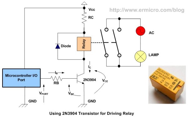
C. Increasing the Collector Current
What if the load current is more than 1 A, let’s say you want to drive a DC motor? Perhaps you will think to use bigger transistor such as 2N3055 power transistor; unfortunately the big power transistor tends to have small hFE mostly less then 20, so it’s mean we have to supply bigger base current. We know that most microcontrollers I/O port can only supply a current up to 20mA, therefore by using this type of transistor the maximum current that we could achieve in the collector terminal is about 400mA; which is far bellow our expectation. The solution for this situation is to use what known as Darlington pair circuit:
By using the Darlington pair circuit we could combine two transistors; one with high hFE2 factor usually has a low collector current and the one with high collector current usually has a low hFE1factor. This will give you a total hFE of hFE1 x hFE2. In the Darlington pair circuits the VBE will be twice the normal transistor saturated voltage which is about 1.4 Volt. One of the popular ready made Darlington pair transistors on the market are TIP120 (NPN type) and TIP125 (PNP type) which could handle the collector current up to 3 A (max 5 A), and has the hFE minimum of 1000.
The TIP120 and TIP125 is called a pair Darlington transistors as they have similar characteristic but have an opposite type (i.e. NPN and PNP), this Darlington transistor pair is popular used in motor controller with the H-Bridge circuit. Remember when you use a power transistor to drive a large collector current, you need to supply the transistor with the adequate heat sink to help cooling the transistor by dissipating heat through the heat sink surface into the surrounding air.
Using the same principal we’ve learned before, we could easily calculate the RB value of the DC motor circuit interface bellow:
By using 5 Volt power supply and DC Motor with 12 Volt and 1 A maximum operating current:
RC = 0 Ohm (not use, connect directly to the 12 Volt power)
IB = IC / hFE = 1 A / 1000 = 0.001 A
RB = (VPORT – VBE) / IB = (4.2 – 1.4) / 0.001 = 2800 Ohm, use 2K7 Ohm resistor
P = (VPORT – VBE) x IB = (4.2 – 1.4) x 0.001 = 0.0028 watt, use 0.25 Watt resistor
D. The Darlington Transistor Array
For more compact version of the Darlington pair transistor you could use the Texas Instrument ULN2803A which is contain 8 Darlington pair transistors with has build in 2K7 base resistor and clamp diode for each Darlington pair transistors. This makes this Darlington transistor array suitable for driving the relay or motor up to 500mA (this is a maximum datasheet value) directly from the microcontroller output.
For more detail: Using Transistor as a Switch