Summary of UART Communication using PIC Microcontroller
Summary: This tutorial explains enabling UART (USART) on the PIC16F877A to transfer serial data between the microcontroller and a PC. It covers asynchronous 8-bit UART setup, wiring (Tx RC6, Rx RC7, common ground), required hardware/software, use of an RS232-to-USB converter and testing via HyperTerminal, and demonstrates toggling an LED from the PC with status feedback.
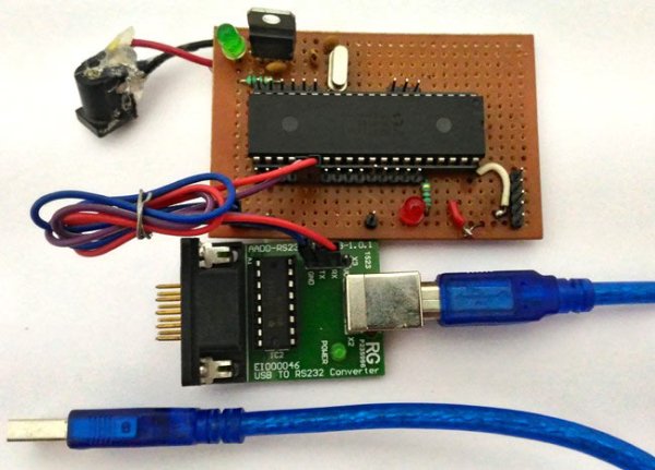
Parts used in the UART Communication with PIC16F877A:
- PIC16F877A Perf Board
- RS232 to USB converter Module
- Computer
- PICkit 3 Programmer
- MPLABX (software)
- HyperTerminal (software)
In this tutorial we learn to Enable UART communication with PIC Microcontroller and how to transfer data to and from your Computer. So far, we have covered all basic modules like ADC, Timers, PWM and also have learnt how to interface LCDs and 7-Segment displays. Now, we will equip our self with a new communication tool called UART which widely used in most of the Microcontroller projects. Check here our complete PIC Microcontroller Tutorials using MPLAB and XC8.
Here we have used PIC16F877A MCU, it has a module called “Addressable Universal Synchronous Asynchronous Receiver and Transmitter” shortly known as USART. USART is a two wire communication system in which the data flow serially. USART is also a full-duplex communication, means you can send and receive data at the same time which can be used to communicate with peripheral devices, such as CRT terminals and personal computers.
The USART can be configured in the following modes:
- Asynchronous (full-duplex)
- Synchronous – Master (half-duplex)
- Synchronous – Slave (half-duplex)
There are also two different modes namely the 8-bit and 9-bit mode, in this tutorial we will configure the USART module to work in Asynchronous mode with 8-bit communication system, since it is the most used type of communication. As it is asynchronous it doesn’t need to send clock signal along with the data signals. UART uses two data lines for sending (Tx) and receiving (Rx) data. The ground of both devices should also be made common. This type of communication does not share a common clock hence a common ground is very important for the system to work.
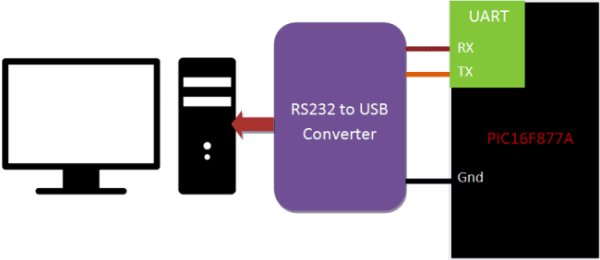
At the end of this tutorial you will be able establish a communication (UART) between your computer and your PIC Microcontroller and toggle an LED on the PIC board from your laptop. The status of the LED will be sent to your laptop from the PIC MCU. We will test the output using Hyper Terminal in computer. Detailed Video is also given at the end of this tutorial.
Requirements:
Hardware:
- PIC16F877A Perf Board
- RS232 to USB converter Module
- Computer
- PICkit 3 Programmer
Software:
- MPLABX
- HyperTerminal
A RS232 to USB converter is required to convert the serial data into computer readable form. There are ways to design your own circuit instead of buying your own module but they are not reliable as they are subjected noise. The one which we are using is shown below
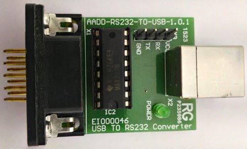
Note: Each RS232 to USB converter would require a special driver to be installed; most of them should get installed automatically as soon as you plug in the device. But, if it doesn’t relax!!! Use the comment section and I will help you out.
Programming PIC Microcontroller for UART Communication:
Like all modules (ADC, Timer, PWM) we should also initialize our USART module of our PIC16F877A MCU and instruct it to work in UART 8-bit communication mode. Let’s define the configuration bits and start with the UART initialization function.
Initializing the UART module of the PIC Microcontroller:
The Tx and Rx pins are physically present at the pins RC6 and RC7. According to datasheet let’s declare TX as output and RX as input.
Read More: UART Communication using PIC Microcontroller
- What MCU is used in this tutorial?
The PIC16F877A microcontroller is used in this tutorial. - How is UART configured in this tutorial?
The USART is configured in asynchronous mode with 8-bit communication. - Which pins are used for Tx and Rx on the PIC16F877A?
Tx is on RC6 and Rx is on RC7 as declared according to the datasheet. - Do the devices need a common connection besides Tx and Rx?
Yes, the ground of both devices must be common for the communication to work. - What hardware is required to connect the PIC to a computer?
An RS232 to USB converter module is required to convert serial data to a computer readable form. - Which software tools are used for programming and testing?
MPLABX is used for programming and HyperTerminal is used for testing the UART communication. - Can the PIC send and receive data at the same time?
Yes, USART is full-duplex so it can send and receive data simultaneously. - What example application is demonstrated in the tutorial?
Toggling an LED on the PIC board from the computer and sending the LED status back to the laptop is demonstrated.