
Summary of Tape Head Pre-Amplifier
This article describes a tape head pre-amplifier circuit centered on the Sanyo LA3161 stereo IC. It details how low-level signals from playback heads are processed through DC decoupling capacitors and equalization components for normal tape playback. The design features a built-in voltage regulator for low noise and ripple rejection, operates on 9–12 VDC, and includes mounting holes, Berg pins, and an LED indicator on a compact PCB.
Parts used in the Tape Head Pre-Amplifier:
- Sanyo LA3161 stereo head preamp IC
- DC decoupling capacitors
- Equalization components
- Berg pins
- Power-On LED indicator
- PCB with four mounting holes
Description
The circuit is built around a popular Sanyos stereo head preamp IC LA3161. Low electrical signals from the playback heads are fed to pins 1 and 8 of IC1 via DC decoupling capacitors, respectively. Components between pins 2 and 3 and pins 6 and 7 provide adequate equalization to the signals for a normal tape playback.
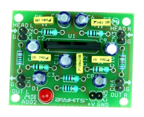
Specifications:
Power supply: 9 ~ 12 VDC @ 20 mA
Output power: upto 200 mW
Input Resistance – 100 KΩ (Typ), Load Resistance – 10 KΩ (Typ)
Low noise, good ripple rejection owing to the on-chip voltage regulator
Berg pins for connecting power supply, input and output
Power-On LED indicator
Four mounting holes of 3.2 mm each
PCB dimensions 49 mm x 38 mm
For more detail: Tape Head Pre-Amplifier
- What is the main integrated circuit used in this project?
The circuit is built around the popular Sanyo LA3161 stereo head preamp IC. - How are low electrical signals from the playback heads connected?
Signals are fed to pins 1 and 8 of IC1 via DC decoupling capacitors. - Which pins provide adequate equalization for normal tape playback?
Components between pins 2 and 3 and pins 6 and 7 provide the necessary equalization. - What is the required power supply voltage for this circuit?
The circuit requires a power supply of 9 to 12 VDC at 20 mA. - Does the IC include a voltage regulator?
Yes, the IC has an on-chip voltage regulator that ensures low noise and good ripple rejection. - What type of connectors are used for power supply and I/O connections?
Berg pins are used for connecting the power supply, input, and output. - Are there any visual indicators included in the design?
A Power-On LED indicator is included in the circuit. - What are the dimensions of the printed circuit board?
The PCB dimensions are 49 mm by 38 mm.

