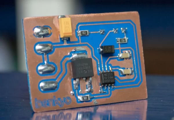
Summary of Surface-mount 555 PWM circuit
This article details a DIY project where the author built a surface-mount 555 PWM circuit to dim room LED lighting. The goal was to learn soldering SMD components on home-etched PCBs and avoid messy perfboards. The design uses 1206 resistors and capacitors, with specific mention of a 22µF tantalum capacitor for the Vcc line. The circuit operates at roughly 1KHz, supports 5V–30V input, and achieves a duty cycle between 10% and 90%.
Parts used in the Surface-mount 555 PWM circuit:
- 555 Timer IC
- Potentiometer
- Surface-mount 1206 resistors
- Surface-mount 1206 capacitors
- 22µF Tantalum capacitor
- MOSFET
- Home-etched PCB
- External flux
Introduction
I wanted to dim my room LED lighting with a potentiometer, and decided on creating a solution from scratch to make it more fun and educative. I decided to go with the fairly well-known 555 PWM circuit. To decrease size and for learning purposes I decided on using surface-mount components for the first time. The reason I wanted to make this 555 PWM circuit is actually just to see if I could solder SMD components on home-etched PCB’s, and to see how hard it actually is.
Working with breadboards is really great, and you can very easily prototype your circuit and swap out components. However, after a while you might want something more permanent, so you grab the good old perfboard, and things get a lot more nasty, with wires sticking out everywhere. After having some experience with PCB milling, I wanted to give etching a shot. And having plenty of soldering experience, I decided on using surface-mount components.
To make soldering easier, I decided on using 1206 resistors and capacitors, except for the 22µF tantalum capacitor used for the Vcc line. Also not having a solder mask will make things a bit more messy, I had to use some external flux to make sure the solder flowed nicely.
Specifications
- Operates at roughly 1Khz
- Voltage range 5v – 30v
- 100mV ripple @ 1A
- At least 2A continuous current without heat sink on MOSFET
- Duty cycle from ~10% – ~90%
As you can see, the duty cycle is not that good. It doesn’t go fully off or on, I already saw this on the breadboard, but decided it didn’t matter because I wanted a simple circuit with average performance.
For more detail: Surface-mount 555 PWM circuit
- Why did the author choose to build this circuit from scratch?
The author wanted to make it more fun and educative while learning to solder SMD components on home-etched PCBs. - What type of components were used for the first time in this project?
Surface-mount components were used for the first time to decrease size and aid learning. - Which resistor and capacitor sizes were selected to make soldering easier?
1206 resistors and capacitors were chosen to facilitate easier soldering. - What is the operating frequency of the circuit?
The circuit operates at roughly 1Khz. - What voltage range does the circuit support?
The circuit supports a voltage range from 5v to 30v. - How much ripple occurs at 1A current?
The circuit produces 100mV ripple at 1A. - Can the MOSFET handle 2A continuous current without a heat sink?
Yes, the MOSFET can handle at least 2A continuous current without a heat sink. - What is the achievable duty cycle range for this design?
The duty cycle ranges from approximately 10% to 90%. - Why was external flux necessary during assembly?
External flux was needed because the lack of a solder mask made the process messy and required help to ensure the solder flowed nicely.