Summary of SIMPLE AUTO ROBOT PIC16F628 H-BRIDGE MOTOR DRIVER CIRCUIT
This article describes a simple auto robot project using the Microchip PIC16F628 microcontroller. The circuit features right and left controls for an open car robot, utilizing an H-bridge motor driver with BD series low-power transistors to manage motor speed. The project includes assembly source code, hex files, PCB layouts, and schematic diagrams. It operates on a 4.5V to 5V power supply or via battery.
Parts used in the Auto Robot PIC16F628:
- PIC16F628 microcontroller
- H-Bridge motor driver
- BD series low-power transistors
- Right control key
- Left control key
- Sprint layout PCB drawing
- Spline drawing scheme
- 4.5V or 5V power supply
- Battery
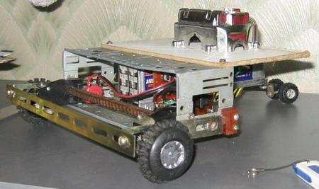
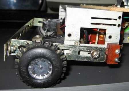
Microchip PIC series microcontrollers prepared with a very robotic circuit’s this circuit compared to the others a bit more simple, right, left controls the keys is done with the development of an open car… Electronics Projects, Simple Auto Robot PIC16F628 H-Bridge Motor Driver Circuit “microchip projects, microcontroller projects, pic16f628 projects, “
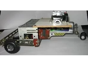
Microchip PIC series microcontrollers prepared with a very robotic circuit’s this circuit compared to the others a bit more simple, right, left controls the keys is done with the development of an open car robot circuit to control the PIC16F628 used motor speed as the bridge is driven driver transistors in the BD series low-power transistors can use
Auto robot project assembly prepared by the PIC source software has asm and hex codes sprint layout pcb drawing of the robot project and spline drawing the scheme have 4.5 or 5v power supply circuit or battery operated.
Read More: SIMPLE AUTO ROBOT PIC16F628 H-BRIDGE MOTOR DRIVER CIRCUIT
- What microcontroller is used in this auto robot project?
The project uses the PIC16F628 microcontroller from the Microchip PIC series. - How are right and left controls implemented in the circuit?
Right and left controls are handled by keys within the development of an open car robot circuit. - Which transistors are used for the motor driver?
BD series low-power transistors are used as drivers in the H-bridge to control motor speed. - Can this robot be powered by a battery?
Yes, the circuit can be operated using a battery or a 4.5V to 5V power supply. - Does the project include software source code?
Yes, the project assembly prepared by the PIC includes ASM and HEX codes. - Are PCB designs available for this robot?
Yes, sprint layout PCB drawings and spline drawing schemes are included in the project. - Is this circuit considered complex compared to others?
No, the article states that this robotic circuit is a bit more simple compared to others. - What voltage range does the power supply require?
The power supply circuit requires either 4.5V or 5V.