Summary of PWM MOTOR CONTROL CIRCUIT HPWM PIC16F876 FREQUENCY MODULATED
This article presents an adjustable frequency PWM motor control circuit utilizing a PIC16F876 microcontroller and HPWM hardware. The design employs IRF540N MOSFETs driven by TLP250 isolators to ensure safety, supporting supply voltages up to 24V with a recommended 15V operation. The system allows frequency adjustment up to approximately 10.4kHz to minimize audible noise while maintaining motor efficiency at lower frequencies.
Parts used in the Adjustable Frequency PWM Motor Control Circuit:
- PIC16F876 Microcontroller
- HPWM Hardware
- IRF540N MOSFETs
- TLP250 Mosfet Driver
- 3Amp Diode
Hello friends. Recent studies have adjustable frequency PWM motor control circuit that I want to share with you. Circuit is designed using pic16f876 and HPWM hardware. I used IRF540N MOSFETs in the payload. Mosfet… Electronics Projects, PWM Motor Control Circuit HPWM PIC16F876 Frequency Modulated”microchip projects, microcontroller projects, motor control circuit, motor driver circuit, pic16f876 projects, picbasic pro examples, pwm circuits, “
Hello friends.
Recent studies have adjustable frequency PWM motor control circuit that I want to share with you.
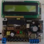
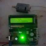
Circuit is designed using pic16f876 and HPWM hardware. I used IRF540N MOSFETs in the payload. Mosfet Mosfet driver I used to drive the TLP250. With mCi TLP250 to the payload portion is fully insulated with chassis. The motor with electronic cards are given separately.
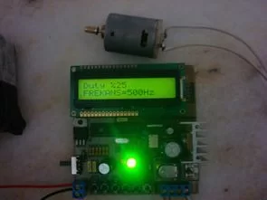
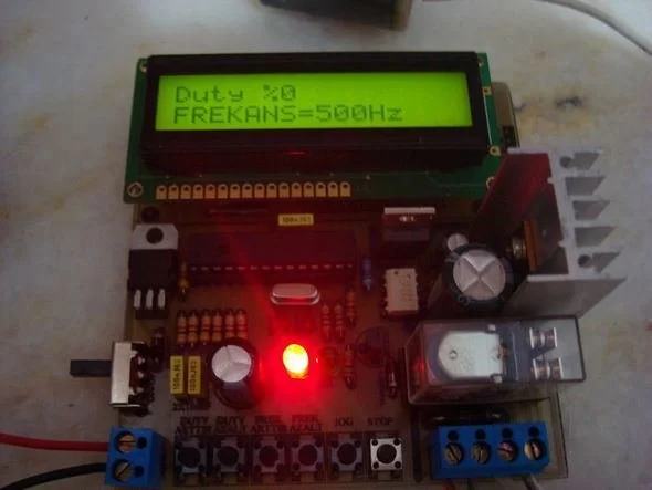
Max.24 volt supply to the engine is provided. ‘ll Use 15volt supply voltage according to the motor can provide 24 volts. Also, your engine can adjust according to the PWM frequency.
Normally I use a 12 volt motor is small for a small engine efficiency at high frequencies did not get much. If the reason was to remain low supply voltage. Max. Get our frequency 10416hz which there was no sound from the engine. But the falling value of 90 and was beginning to turn over the engine.
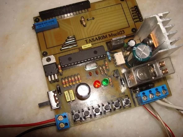
Finally, let me specify some points to consider friends. I use mine in the vicinity of the motor nominal current is 1 amp power supply input for the engine 3Amp diode’m currently using. If you are using the engine more current çekşy you absolutely must slightly change the payload.
Source: PWM MOTOR CONTROL CIRCUIT HPWM PIC16F876 FREQUENCY MODULATED All files belonging to the motor control circuit: pwm-motor-control-circuit-hpwm-pic16f876-frequency-modulated.RAR
- What components are used for motor control?
The circuit uses a PIC16F876 microcontroller and HPWM hardware. - How is the motor driver isolated?
The TLP250 driver is used to fully insulate the payload portion from the chassis. - What is the maximum supply voltage supported?
The engine can be provided with a maximum of 24 volts. - Can the PWM frequency be adjusted?
Yes, the engine speed can be adjusted according to the PWM frequency. - What is the maximum frequency achieved without sound?
The maximum frequency reached was 10416Hz where there was no sound from the engine. - At what frequency does the engine begin to turn over?
The falling value of 90 began to turn over the engine. - What diode current rating is recommended for a nominal 1 amp motor?
A 3Amp diode is currently used for the engine input power supply.