


Summary of Pinguino Egypt – PIC Based Arduino
The author details the construction of a custom PIC18F4550-based board compatible with Arduino, inspired by Pinguino. After years of experience with Microchip microcontrollers and recent exposure to Arduino, the project aims to create an easy-to-build, versatile circuit. The process involves sourcing specific components, soldering them onto a copper board, and installing a bootloader via a JDM programmer to enable USB communication and self-updating capabilities without further external programmers.Parts used in the Pinguino Egypt Project:
- Copper Board (VeroBoard or Stripboard or Perfboard)
- PIC 18F4550 Microcontroller
- 40 Pin IC Socket
- USB Type B Socket
- 20MHz Crystal
- 220nF Capacitor
- 100nF Capacitor
- 2 22pF Capacitors
- Push Button
- Dip Switch
- 10k Ohm Resistor
- 7805 Voltage Regulator
- 9v Battery Connector
- Female Pin Header
- 1N4001 Diode
- 2 Rows of Pin Headers
Recently, I started reading and trying some Arduino.
I really wished to build a similar circuit based on the Microchip PIC. Even I started to think to design a circuit of my own. I searched online and I found Pinguino.
Just like Arduino , there are many versions of Pinguino using different Microcontrollers from Microchip. I wanted to build the version using PIC18F4550.
I found Pinguino before this time and saw it among many other Arduino clones , but this time was really different.
I was ready to start making circuits with the PIC18F4550 chip after I completed building the PIC18F4550 programmer .
So I decided to start from where the others have reached.
I 've decided to build this magnificent circuit that brings all my dreams together,
PIC based , Arduino compatible and Easy-to-build.
I was such excited to build it and try all Arduino projects with it. So, I started to collect the data and components to start working.
I also wanted to try the PC Software/Embedded Software communication.
Although I was determined to build the circuit on a copper board to stay with me and use it many times, I wanted to quickly assemble it on a bread board to try it ASP !!!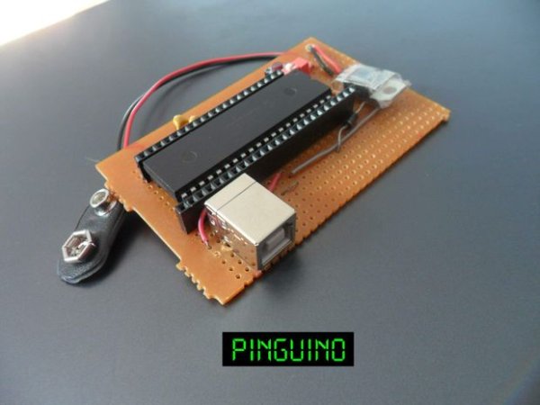
Here are some useful links:
http://wiki.pinguino.cc/index.php/PIC18F4550_Pinguino
http://wiki.pinguino.cc/index.php?title=File:Pin_pinguino_18F4550_%282%29.png&limit=500
http://www.hackinglab.org/pinguino/
https://sites.google.com/site/pinguinotutorial/home
بدأت تعلم المتحكم الدقيق منذ إحدى عشر عاماً . و كان أول ما تعلمته هو المتحكم الدقيق من عائلة
Microchip
و منذ فترة قصيرة حاولت تجربة الاردوينو و كنت أود تصميم دائرة الكترونية بسيطة مشابهة باستخدام المتحكم الدقيق من عائلة
Microchip
يمكنك قراءة هذه المقالة باللغة العربية
http://arabic-embedded-egypt.blogspot.com/2014/03/pinguino-egypt.html
You can find this instructable on my blog :
Step 1: Components
Material I built my board with :
1 Copper Board ( VeroBoard or Stripboard or Perfboard )
1 PIC 18F4550
1 40 Pin IC Socket
1 USB Type B Socket
1 20MHz Crystal
1 220nF Capacitor
1 100nF Capacitor
2 22pF Capacitors
1 Push Button
1 Dip Switch
1 10k Ohm Resistor
1 7805 Voltage Regulator
1 9v Battery Connector
1 Female Pin Header
1 1N4001 Diode ( or any other general purpose diode )
2 Rows of Pin Headers
The first circuit is the circuit diagram on the Pinguino website.
And the second circuit is the one I 've built in detail.
Step 2: Start Soldering
There are many instructables and other online tutorials for soldering.
I used a large verro board because I didn't know how exactly the circuit will occupy.
I started to solder the components on the board.
After I finished assembling and soldering, I used an architects saw to cut the board into the size which the components actually fit into. 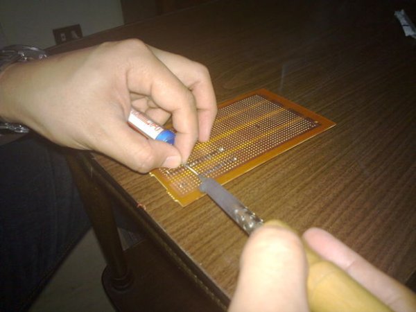
Step 3: Install Pinguino Boot loader
The boot loader is the initial software that enables the Microcontroller to communicate with the PC through the USB port.
It also enables the Microcontroller to self update its software sent on the USB port.
This is the link were you can get the boot loaders of your circuit. In my circuit, I 've chosen the PIC18F4550 Microcontroller with the 20MHz Crystal
http://pinguino32.googlecode.com/svn/bootloaders/8/usb/v4.x/hex/
The 18F4550 Microcontroller chip is a self programming Microcontroller.
This means that the Pinguino board can be used to update its Firmware to a new one making it capable of doing a new function.
Initially , the Microcontroller cannot directly communicate with PC using USB port. But it can be programmer as a normal Microcontroller.
You can program your chip on an external USB or Serial Microcontroller programmer.
You have to do this step only once. After this, when completing Pinguino, you will not have to use a programmer any more.
I installed the bootloader using a simple programmer I previously built. It is called JDM Programmer .
You can build it your self. It is simple and direct.
Here is a link for the Instructable of the programmer
http://www.instructables.com/id/18F4550-Programmer-in-Ten-years/
I used the PicPGM programmer with my serial JDM programmer to load the target bootloader file (Bootloader_v4.13_18f4550_X20MHz.hex)
After successfully install the Bootlader Hex file on the Microcontroller chip , you can insert it into the Pinguino board.
Congratulations , you have completed the Pinguino board Hardware part !!
For more detail: Pinguino Egypt - PIC Based Arduino
-
What is the main goal of this project?
The goal is to build a PIC-based, Arduino-compatible, and easy-to-build circuit using the PIC18F4550 chip. -
How does one initially program the microcontroller before the bootloader is installed?
You must use an external USB or Serial Microcontroller programmer because the chip cannot directly communicate with a PC via USB initially. -
What tool was used to cut the copper board to size?
An architects saw was used to cut the board into the size which the components actually fit into. -
Can the Pinguino board update its own firmware after the bootloader is installed?
Yes, the PIC18F4550 is a self-programming microcontroller that allows the board to update its software sent on the USB port. -
Which specific bootloader file was mentioned for the 20MHz crystal setup?
The Bootloader_v4.13_18f4550_X20MHz.hex file was used. -
Is it necessary to keep using an external programmer after installing the bootloader?
No, once the bootloader is successfully installed, you will not have to use a programmer anymore. -
What type of socket is required for the PIC 18F4550 chip?
A 40 Pin IC Socket is required.
Related projects
PICDEM FS USB CDC Evaluation Board using PIC18F4550 with Proteus Simulation
Introduction The PICDEM FS USB CDC Evaluation Board is a practical microcontroller project built around the PIC18F4550, designed to demonstrate USB communication...
Peripheral Tutorials · PIC18F4550PICDEM FS USB Mass Storage Device using PIC18F4550 with Proteus Simulation
Introduction This microcontroller project demonstrates how to simulate a USB Mass Storage Device (MSD) using the PIC18F4550 in a Proteus simulation environment....
Development Boards & Kits · PIC18F2550Pinguino Project: A PIC Microcontroller Based Arduino
This is a complete tutorial to make a PIC Microcontroller based Arduino. This is a complete tutorial to make PIC microcontroller based...
Development Boards & Kits · PIC18F4520Voltage Measurement with A PIC Microcontroller
Voltage Measurement with PIC Microcontroller articulates a methodical framework for facilitating analog voltage measurement using the PIC18F4520, an advanced member of Microchip’s...
Development Boards & KitsUltra-Low Power: Microcontroller Standby Current to 130uA with OPEnS Power Control Board
At the OPEnS Lab, a key focus for our projects is achieving exceptionally long battery life. This was particularly true for the...
Development Boards & KitsAn Integrated Approach to Developing Applications with Microchip PIC Microcontrollers
1. Introduction In our daily lives, a variety of devices such as telephones, household appliances, and cars incorporate "smart" electronics, typically manifested...

Ibrar Ayyub
I am an experienced technical writer holding a Master's degree in computer science from BZU Multan, Pakistan University. With a background spanning various industries, particularly in home automation and engineering, I have honed my skills in crafting clear and concise content. Proficient in leveraging infographics and diagrams, I strive to simplify complex concepts for readers. My strength lies in thorough...