Summary of PICs in Space
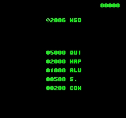
This article details a DIY Space Invaders game built around a PIC16F628A microcontroller. It features full-color graphics, animated invaders, stereo sound, and progressive difficulty on 50Hz RGB SCART televisions. The design requires no active components besides the MCU, using standard retro joysticks and offering non-volatile high scores.
Parts used in the PICs in Space Game:
- Microchip PIC16F628A microcontroller
- Battery
- Power switch
- Decoupling capacitors
- Three buttons with pull-up resistors
- 9-pin D connector
- Atari-style digital joystick
- 20MHz crystal (or ceramic resonator)
- Load capacitors
- Resistors and capacitors for signal matching
- LED indicator
- Fully-wired SCART lead
Features
- Full colour
- Animated invaders
- High-resolution display
- High-quality stereo sound effects
- Non-volatile high score table
- High-tech rolling score
- Mother ship with random score
- Progressively increasing speed and difficulty
- Realistic shield damage
- Bonus lives
- Compatible with 625-line/50Hz televisions that have an RGB SCART input
- Uses standard retro Atari-style joystick
- Solid interlaced display
- Accurate synchronisation waveforms, including serration and equalisation
 Hardware
The circuit diagram is shown to the right. You can get a larger version or a PostScript version if you prefer. The design is based around a Microchip PIC16F628A microcontroller. At the time of writing, this device is available for less than one pound from (among others) Crownhill Associates. All the work, including colour video and synchronisation signal generation, is done in the microcontroller, and so there are no other active components. Purists who contend that the LED is an active component may replace it with a light bulb.
We will describe the circuit from left to right. On the far left of the circuit diagram are the battery, power switch and decoupling capacitors. The smaller decoupling capacitor should be wired as close to the power pins of the microcontroller as possible.
Three buttons with pull-up resistors provide the game controls. We have shown the buttons wired in parallel with a 9-pin D connector, into which you can plug an Atari-style digital joystick. You can of course dispense with either the buttons or the connector if you wish.
The connector to the above left of the microcontroller is for in-circuit programming of the device. You may need to change this part of the circuit to suit your programmer. Note that MCLR must be pulled high and RB4 pulled low for normal operation.
The microcontroller derives its clock from a 20MHz crystal. The load capacitor values shown should be suitable for most readily-available crystals. A ceramic resonator could be used instead of the crystal, and should be accurate enough to allow most televisions to lock on to the resulting signal.
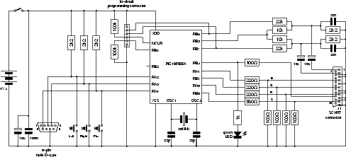 On the right, a handful of resistors and capacitors match the audio (top right) and video (bottom right) signal levels to those required by the television. Crude anti-alias filtering is provided for the audio. The LED lights when the microcontroller takes the RGB select pin on the SCART connector high: this occurs shortly after power-up, and so the LED provides some indication that the circuit is functioning correctly.
Note that the SCART lead you use to connect the game to your television must be fully-wired: not all leads carry the RGB signals. Your television must also be capable of accepting the RGB signals. Most modern televisions have at least one SCART input with this facility, though you may need to check the manual (or experiment) to determine which one it is.
For more detail: PICs in Space
- What is the main component used in the circuit?
The design is based around a Microchip PIC16F628A microcontroller. - Can I use a ceramic resonator instead of a crystal?
A ceramic resonator could be used instead of the crystal and should be accurate enough to allow most televisions to lock on. - Does the game support stereo sound?
Yes, the project includes high-quality stereo sound effects. - What type of television input is required?
The game is compatible with 625-line/50Hz televisions that have an RGB SCART input. - How are the game controls implemented?
Three buttons with pull-up resistors provide controls, wired in parallel with a 9-pin D connector for an Atari-style joystick. - Is the display solid or interlaced?
The project provides a solid interlaced display with accurate synchronisation waveforms. - Can I replace the LED with another component?
Purists may replace the LED with a light bulb as it is considered an active component. - What happens if the SCART lead is not fully-wired?
If the lead is not fully-wired, it will not carry the RGB signals required by the game. - How does the game handle difficulty?
The game features progressively increasing speed and difficulty levels. - Is there a way to save high scores?
Yes, the system includes a non-volatile high score table.