Experimental circuit board modules can be made quickly and fairly easily. They have the advantage of being more than twice as fast to build than a custom circuit board. They are also easy to test in a breadboard. The modules detailed here are ones I have made using various Picaxe microcontrollers.
Step 1: Picaxe Project Modules
Pic2 shows a few of the Picaxe modules that I have built and tested that use the Picaxe microcontroller. They are designed to be modular so that they can be plugged into different robots that are being worked on. It takes a lot of time to create a new robot and they often have many of the same basic circuits and programming of a previously built robot. If simple modules that easily interface with each other are built, new robot ideas and configurations can be more quickly tried out.
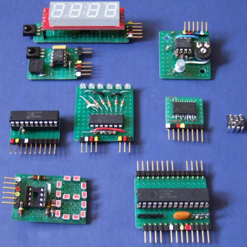
2a- An infrared receiver that can receive and output numbers from a remote control or Picaxe based robot.
2b- An infrared receiver that outputs sounds such as beeps and buzzes. The little square in the lower left hand corner of the board is a speaker that is actually quite loud.
2c-A 20x-2 Picaxe microcontroller. This is my favorite Picaxe as it can run at 64 mh and it does not require resistors at the inputs to keep it stable.
2d- A music visualizer that flashes when words are spoken. It connects directly to an 8 ohm speaker or mp3 output.
2e- A picaxe 08m using four of its outputs which are charlyplexed to LEDs to output 0-9
2f-An RGB voltmeter using an 08m which produces different colors for different voltages. For schematic and some details see here: http://www.inklesspress.com/picaxe_projects.htm
2g- a smaller version of the 20x-2 Picaxe which uses a SOIC version of the microcontroller.
2h- A picaxe 28x-2 which is crystal controlled and has access to all inputs and outputs.
2i- A live bug version of the 08m which has surface mount resisters mounted on top so the microcontroller can be plugged into a breadboard or socket.
Step 2: Materials
FR-4 solid line perfboard from: http://www.allelectronics.com/
Available from mouser.com:
magnet wire
.1″ headers and sockets
drill bit
components for your particular circuit
Picaxe microcontrollers available from sparkfun.com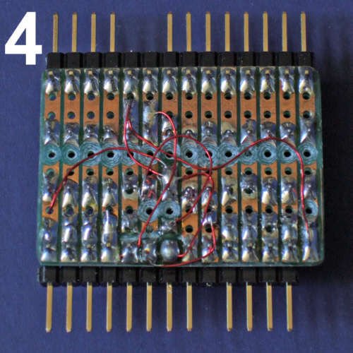
Step 3: Making Fast Printed Circuit Modules
In less time than it takes to layout a custom circuit board in a PC, print out the pattern and etch it, I can usually wire up a perfboard module and test it.
The solid line perfboard is made of fiberglass so it is stable. It it predrilled and the copper cladding pre etched into parallel lines. First you solder in the main components. Then, all you need to do is cut the lines you don’t need, and add wires wherever you need them.
Pic3 shows a 28x-2 Picaxe controller module. It has grounded resistors to keep its inputs from floating and headers to provide access to all it pins.
pic4 shows the bottom of the circuit board. The continuous copper traces are drilled out with a 1/8″ drill bit or cut with a knife wherever a break is needed. 30 gauge magnet wire is used for jumpers to complete the circuit. With careful layout on a module, very few jumper wires are usually needed.
I usually color code the headers that go to power and the serial in and serial out programming pins.
For more detail: Picaxe Projects #1: Making Fast Printed Circuit Modules