Summary of PIC16F877 timer0 code and Proteus simulation
This article explains how to configure and use Timer0 interrupts on a PIC16F877 microcontroller using C language. It details a circuit setup with a 20MHz crystal where the RB0 pin toggles upon timer expiration, verified via Proteus simulation. The code is compiled in MPLAB with HI-TECH C.
Parts used in the PIC16F877 Timer0 Project:
- PIC16F877 Microcontroller
- 20MHz External Crystal
- RB0 Pin
- Proteus Simulator (v7.10)
- MPLAB IDE (v8.85)
- HI-TECH C Compiler (v9.83)
This PIC16F877 microcontroller tutorial answers the question,
” How to use timer0 of PIC16F877 and how to handle its interrupts? ”
Using PIC16 simulator (Proteus) you can verify this PIC timer0 code and change it according to your needs. This code is written in C language using MPLAB with HI-TECH C compiler. You can download this code from the ‘Downloads‘ section at the bottom of this page.
It is assumed that you know how to blink an LED with PIC16F877 microcontroller. If you don’t then please read this page first, before proceeding with this article.
The following diagram (made in Proteus) shows the PIC microcontroller circuit diagram.
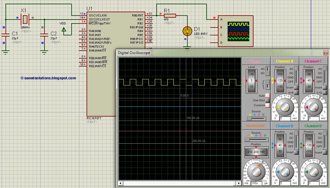
In this circuit, PIC16F877 is running on external crystal of 20MHz value. RB0 pin is toggled every time timer0 expires and executes it’s ISR[1] code. In the above figure, it is clear that after approximately every 100usec, RB0 pin is toggled i-e timer0 expires. You can easily change this value in the code.
Code
The main function code is shown below.
Downloads
Timer0 code for PIC16F877 was compiled in MPLAB v8.85 with HI-TECH C v9.83 compiler and simulation was made in Proteus v7.10. To download code and Proteus simulation click here.
For more detail: PIC16F877 timer0 code and Proteus simulation
- How to use timer0 of PIC16F877?
You can use it by writing code in C language using MPLAB with HI-TECH C compiler to handle its interrupts. - Can you verify the code using Proteus?
Yes, you can verify this PIC timer0 code using the PIC simulator Proteus and change it according to your needs. - What value does the external crystal have?
The PIC16F877 in this circuit runs on an external crystal of 20MHz value. - Does the RB0 pin toggle every time timer0 expires?
Yes, the RB0 pin is toggled every time timer0 expires and executes its ISR code. - How often does the timer expire in the described circuit?
After approximately every 100usec, the timer0 expires and the RB0 pin is toggled. - Can the timer expiration value be changed?
Yes, you can easily change this value in the code. - Which compiler was used for the project?
The code was compiled using HI-TECH C v9.83 within MPLAB v8.85. - What version of Proteus was used for simulation?
The simulation was made in Proteus v7.10.