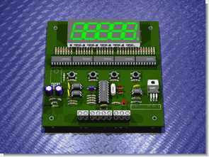
Summary of PIC16F628 MULTI-MODE ENCODER, COUNTER CIRCUITS CCS C
This article describes a PIC16F628-based multi-mode encoder and counter circuit operating at 20MHz. It features three modes: "enc" for millimeter accuracy, "Counter" for value setting, and "disp" for decimeter display. The system detects direction via B output transitions (Low-to-High or High-to-Low) to increment or decrement counts.
Parts used in the PIC16F628 Multi-Mode Encoder:
- PIC16F628 Microcontroller
- Encoder Input
- B Output Pin
- CCS C Compiler
- Proteus ISIS Simulation
- Eagle PCB Design Files
Hello friends, I have done well to share with you the counter circuits as functions istedim.kısa tell. There are three mode of counter: enc: millimeter accuracy in the measurement is made. The value is set in the output data…. Electronics Projects, PIC16F628 Multi-Mode Encoder, Counter Circuits CCS C “ccs c examples, microchip projects, microcontroller projects, pic16f628 projects,
Hello friends, I have done well to share with you the counter circuits as functions istedim.kısa tell. There are three mode of counter:
enc: millimeter accuracy in the measurement is made. The value is set in the output data.
Counter: Counts the amount is set at the value of the output data.
disp: Meter makes measurement, shows decimeter accuracy
You can connect to the encoder input, interrupt b0 rises from 0 to 1 at the moment in a direction B output is 0 if one is going in the other direction. I do not know, but these commands can be prepared from the PLC logic business benefits
example of output at a low level to high levels (Low-to-High) transition in the B output of availability if one direction while rotating B-> LOW other direction while rotating B-> HIGH so that it becomes the direction in which return you will understand that the output of the Low-to-High transitions a If B is looking at the state variable increases HIGH, LOW detract from the
Note: PIC16F628 Set the frequency of 20MHz.
PIC16F628 COUNTER CIRCUITS SCHEMATICS
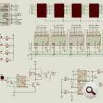
To be @ Picproj forum’s sharing all of the source files in hex isis simulation eagle pcb’s ccs c code and other files
PIC16F628 COUNTER ENCODER MANUAL
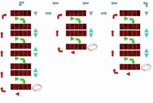
PIC16F628 Multi-Mode Encoder proteus isis simulation schematic proteus ares pcb and CCS C source code files download:
FILE DOWNLOAD LINK LIST (in TXT format): LINKS-5288.zip
Source: PIC16F628 MULTI-MODE ENCODER, COUNTER CIRCUITS CCS C
- What are the three modes of the counter?
The modes are enc for millimeter accuracy, Counter for value setting, and disp for decimeter display. - How does the device determine rotation direction?
It checks if the B output transitions from Low to High or High to Low during rotation. - What frequency is set for the PIC16F628?
The frequency is set to 20MHz. - What happens when the B output goes from Low to High?
The state variable increases if one direction is detected while rotating. - Can I access the source code files?
Yes, CCS C code, hex files, and simulation files are available for download. - Which software tools are mentioned for this project?
The project uses Proteus ISIS, Eagle PCB, and CCS C compiler.