
Summary of PIC12F675 timer1 code and Proteus simulation
This article explains how to configure Timer1 on a PIC12F675 microcontroller using C code in MPLAB with the HI-TECH compiler. It details initializing the timer registers, setting a 1:1 prescaler for a 4MHz internal oscillator, and enabling interrupts to toggle GP0 every 130 milliseconds. The content includes simulation results from Proteus showing the expected output timing.
Parts used in the PIC12F675 Timer1 Project:
- PIC12F675 microcontroller
- Internal oscillator (4MHz)
- GP0 pin
- TMR1H register
- TMR1L register
- T1CON register
- MPLAB IDE
- HI-TECH C compiler
This post provides the timer1 code for PIC12F675 microcontroller. This code is written in C language using MPLAB with HI-TECH C compiler. You can download this code from the ‘Downloads‘ section at the bottom of this page.
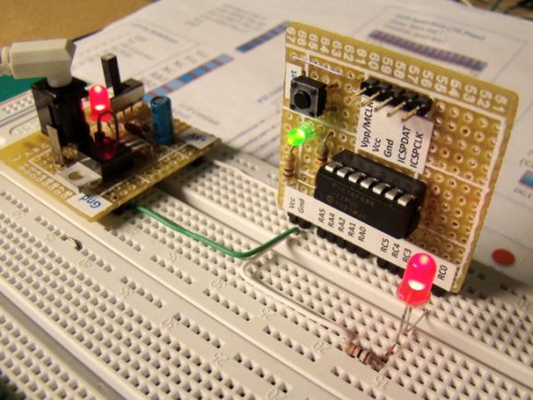
It is assumed that you know how to blink an LED with PIC12F675 microcontroller. If you don’t then please read this page first, before proceeding with this article.
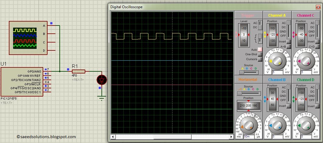
The result of simulating the code in Proteus is shown below.
In this circuit, PIC12F675 is running on internal oscillator of 4MHz value. GP0 pin is toggled every time timer1 expires and executes it’s ISR[1] code. In the above figure, it is clear that after approximately every 130msec, GP0 pin is toggled i-e timer1 expires. You can easily change this value in the code.
Code
The code used to initialize timer1 is shown below.
In this function, firstly timer1 count registers (TMR1H and TMR1L) are cleared before starting timer1. T1CON register is initialized to make timer1 prescalar to be 1:1. Timer1 is a 16bit timer, so it expires after reaching a value of 65535. When timer1 prescalar is made 1:1 then it means that, timer1 value will increment after every clock cycle. Since PIC12F675 is running at 1MIPS[2] speed, this means that timer1 will expire after every 65535*2 = 131 msec[3]. T1IF bit clears any pending timer1 interrupts. T1IE bit enables timer1 interrupts, PEIE bit enables peripheral interrupts (It is a must to enable peripheral interrupts in order to enable timer1 interrupts) and GIE bit enables global interrupts.
Timer1 interrupt service routine code is shown below.
Downloads
Timer1 code for PIC12F675 was compiled in MPLAB v8.85 with HI-TECH C v9.83 compiler and simulation was made in Proteus v7.10. To download code and Proteus simulation click here.
For more detail: PIC12F675 timer1 code and Proteus simulation
- How is the PIC12F675 configured for this project?
The microcontroller runs on an internal oscillator of 4MHz value. - What happens when Timer1 expires?
The GP0 pin is toggled and the interrupt service routine code executes. - How long does it take for Timer1 to expire at 1:1 prescaler?
Timer1 expires after approximately 131 msec or 130 msec. - Which registers are cleared before starting Timer1?
Timer1 count registers TMR1H and TMR1L are cleared. - How is the Timer1 prescaler set in the code?
The T1CON register is initialized to make the prescalar 1:1. - What bits must be enabled to activate Timer1 interrupts?
T1IF clears pending interrupts, T1IE enables Timer1 interrupts, PEIE enables peripheral interrupts, and GIE enables global interrupts. - Why must peripheral interrupts be enabled?
It is a must to enable peripheral interrupts in order to enable Timer1 interrupts. - What software was used to compile the code?
The code was compiled in MPLAB v8.85 with HI-TECH C v9.83 compiler. - Where can I find the simulation results?
The result of simulating the code in Proteus is shown in the article figure.
