Summary of PIC12F675 i2c (bit banging) code and Proteus simulation
This article presents C code for implementing I2C communication via bit-banging on the PIC12F675 microcontroller, which lacks a hardware module. Developed in MPLAB using HI-TECH C, the project uses GP4 as SDA and GP5 as SCL with 10K pull-up resistors. The author validates functionality through Proteus simulation, detailing specific data transmission sequences and timing results observed in the debugger tool.
Parts used in the PIC12F675 I2C Bit Banging Project:
- PIC12F675 microcontroller
- GP4(AN3) pin (SDA)
- GP5 pin (SCK)
- 10K resistors (pull-up)
- I2C Debugger Tool
This post provides the i2c bit banging code for PIC12F675 microcontroller. As we know[1], PIC12F675 microcontroller doesn’t have any built in i2c modules, so we have to create it in the software. This code is written in C language using MPLAB with HI-TECH C compiler. You can download this code from the ‘Downloads‘ section at the bottom of this page.
It is assumed that you know how to blink an LED with PIC12F675 microcontroller. If you don’t then please read this page first, before proceeding with this article. It is also assumed that you know how i2c protocol works, if you don’t then please read this page first.
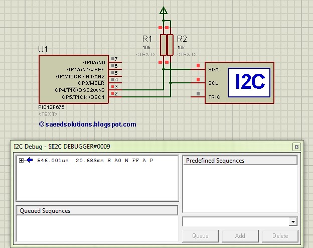
The result of simulating the code in Proteus is shown below.
In the above circuit[2], GP4(AN3) pin is being used as SDA pin and GP5 pin is the SCK pin. Both of these pins are pulled up using 10K resistors as required for i2c protocol. Proteus provides an ‘I2C Debugger Tool‘ which is attached on the SDA and SCK pins in the above circuit. This i2c debugger tool receives all the i2c messages and displays them on the ‘I2C Debug‘ window displayed in above figure. Close up image of this ‘I2C Debug‘ window is shown below in the figure.
In the above figure, ‘I2C Debugger Tool‘ is telling us that first of all it received i2c start bit S. Then a value of 0xA0 was received. After that, there was a NACK bit (named as N in the above figure). After the NACK, a value of 0xFF was there on i2c bus. After that, an ACK was there (named as A) in the above figure, and in the end i2c stop bit (named as P) was received. When this Proteus simulation started then after 546.001usec PIC12F675 started sending this i2c data and stopped at 20.683msec time.
Code
The code for the main function is shown below.
Downloads
I2C code for PIC12F675 was compiled in MPLAB v8.85 with HI-TECH C v9.83 compiler and simulation was made in Proteus v7.10. To download code and Proteus simulation click here.
For more detail: PIC12F675 i2c (bit banging) code and Proteus simulation
- Why is software implementation required for this project?
The PIC12F675 microcontroller does not have any built-in I2C modules. - Which pins are assigned as SDA and SCK?
GP4(AN3) is used as the SDA pin and GP5 is used as the SCK pin. - What value do the pull-up resistors have?
Both SDA and SCK pins are pulled up using 10K resistors. - How long did the simulation take to start sending data?
The PIC12F675 started sending data after 546.001 microseconds. - At what time did the simulation stop?
The simulation stopped at 20.683 milliseconds. - What compiler was used to write the code?
The code was written using the HI-TECH C compiler within MPLAB. - Which tool displays the I2C messages in the simulation?
The Proteus I2C Debugger Tool receives and displays all I2C messages.