Summary of PIC10F200 based dice
This article describes a compact PIC10F200-based electronic dice PCB using surface-mount components, powered from a 9V battery via an LP2985 5V regulator. A PIC10F200 or compatible PIC10F222 drives seven LEDs arranged as a 2x2 matrix with diodes enabling three-pin control and multiplexing at ~100 Hz. The design is low-power (0.4 µA standby), requires SMD soldering skills, and PCBs, preprogrammed chips, and kits are available from the author.
Parts used in the PIC10F200-based dice:
- PIC10F200 or PIC10F222 microcontroller
- LP2985 5V regulator (SOT-23-5)
- 100 nF input capacitor for regulator
- 100 nF output capacitor for regulator
- Seven LEDs
- Series resistors for LEDs
- Diodes for bidirectional matrix wiring
- Push button switch (connected to reset/input pin)
- 9V battery and cable
- PCB with cable strain-relief hole
This page describes a PIC10F200-based electronic dice. The reason I made this was that I got a small corner left over when ordering a panel with a couple of other PCBs and thought I would rather use the corner for something fun than leave it unused, so I made a dice. The PCB is quite small, so it is hard to etch yourself even the layout is available in the zip-file if you want to try, so to make it easier for you I’ve made it possible for you to buy PCBs, preprogrammed chips, and of course complete kits from me in my web shop.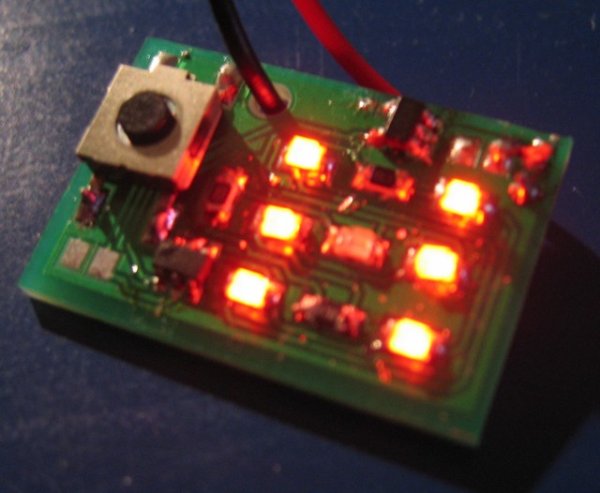
Even though this is a very simple project, it requires some surface mount soldering skills, proper tools, and a steady hand as it is built with surface mounted components only. But it might be a good start if you have experience in hole mounted soldering and want to try surface mount soldering. As you can see in the picture to the right it is possible to make it work even if the soldering looks like crap.
The hardware.
The standard solution for a power supply is to use a 7805 but I could not find any 7805 in a sot-23 or smaller capsule so I used an LP2985 that is available in a 5-pin sot-23 capsule with 5v/150mA output. I use a 100nF cap on both input and output side of the regulator to get rid of noise etc. I’m using a standard 9v battery to supply the circuit. In the PCB-layout there is also a hole for the cable to remove mechanical tension from the soldering point of the cable.
The PIC controlling the dice is a PIC10F20X, but it is also possible to use a PIC10F22X (that is what is sold in my web shop. as it is almost the same price so I use the 10F222 to get fewer chips in stock as other projects use the 10F222), both are microcontrollers with very limited RAM and ROM, 16b/256w of RAM/ROM but there are versions with up to 24b/512w, the 10F22X series also has an ADC but that is not needed in this project. Same .hex-file can be used for both the PIC10F200 and the PIC10F222 as the later is set into compatible mode and only disables the 10F222 specific functions in the beginning of the program which has no effect on a 10F200 chip.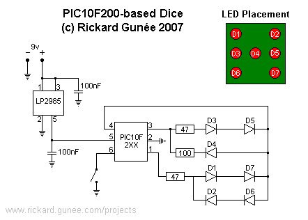 Two of the six pins are used for power supply, there is one reset (or input only) pin and three IO-pins. The switch is connected to the reset pin that is configured as an input. The three IO-pins left is used to drive a 2×2 matrix configuration of the seven LEDs. The LEDs are connected in series and lit in three sets of two LEDs on opposite sides in series and one single LED in the center. The 2×2 matrix configuration is created with three pins only by putting diodes in both directions so when the common line is “0” LEDs are lit by “1” and when the common is “1” LEDs are lit by “0”. This leads to that only two sets of LEDs can be lit at one time, either the LEDs in the corners or the ones in the middle. When changing fast (100Hz) between lighting the different LEDs it look like they are all lit at the same time thanks to the persistence of vision effect. There are of course some resistors in series with the LEDs as the system runs on 5v and the LEDs have a voltage drop of about 2v each.
One nice feature of the PIC10F-series is the current consumption, especially in sleep mode. This removes the need of an on/off switch as the dice only uses 0.4uA in standby, so it can be in standby for many years without discharging the battery.
For more detail: PIC10F200 based dice
- Can I use a PIC10F222 instead of a PIC10F200?
Yes, the same hex file can be used as the 10F222 is set into compatible mode and 10F222-specific functions are disabled. - What power supply is used for the dice?
A standard 9V battery is used with an LP2985 5V regulator. - Why is an LP2985 used instead of a 7805?
Because LP2985 is available in a 5-pin SOT-23 package suitable for the small PCB, unlike a 7805 in that small package. - How are seven LEDs driven with only three IO pins?
The LEDs are arranged in a 2x2 matrix with bidirectional diodes so three pins can multiplex the seven LEDs and light them by switching states and using persistence of vision at about 100 Hz. - Are there resistors for the LEDs?
Yes, series resistors are used because the system runs on 5V and LEDs have about 2V drop each. - Does the design require surface mount soldering skills?
Yes, the PCB uses only surface-mount components and requires SMD soldering skills and proper tools. - Is an on/off switch required for power savings?
No, the PIC10F series has very low sleep current (about 0.4 µA) so an on/off switch is not necessary for long battery life. - Is the PCB layout available for DIY etching?
Yes, the layout is available in the zip file, but the PCB is small and hard to etch yourself; the author also offers PCBs and kits for sale.