
Summary of PIC 16F917 Gyroscope interface
This article explains interfacing an Analog Devices ADXRS613 yaw-rate gyroscope with a PIC16F917 using its ADC module. The ADC reads the sensor's analog output, and firmware converts readings to direction and rate displayed on an LED column; clockwise lights one half, counterclockwise the other. The project uses Hitec C, Proteus 7 simulation (gyroscope emulated by a variable resistor), and adds buzzer tones for right/left rotation.
Parts used in the PIC16F917 Gyroscope interface:
- PIC16F917 microcontroller
- Analog Devices ADXRS613 gyroscope (evaluation EVAL-ADXRS613)
- LED column/LEDs for display
- Buzzer
- Variable resistor (used in Proteus simulation to emulate gyroscope)
- Proteus 7 simulation software
- Hitec C Compiler
In this post we will study the ADC ( Analog-to-Digital ) Module of the Microcontroller PIC16F917 . We will study a real circuit of PIC16F917 interfacing to a semiconductor Gyroscope.
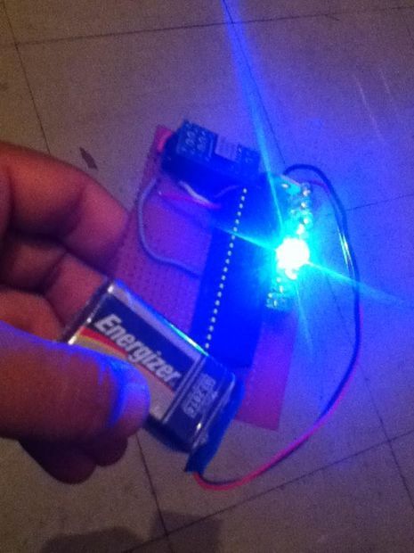
The Gyroscope is a motion sensor that senses tilt in a certain direction . The used sensor is a yaw rate sensor ( free sample from Analog Devices . The Gyroscope ADXRS613 was sent in an evaluation package EVAL-ADXRS613 ) . Yaw means rotation around the vertical access . And rate means the acceleration of this rotational motion.
The output from this sensor is analog signal which represents the Yaw rate in certain direction ( Left or Right ).
The analog signals are converted in the ADC module of the PIC16F917 and are represented on an LED column according to the yaw rate and direction.
The program is very simple and straight forward. It starts by configuring the ports of the Microcontroller for input and output. Then the ADC Module is also configured ( Channel , sampling rate and result data format ).
Then the infinite loop of the program starts which contains the step of
starting the conversion ,
waiting for conversion to complete and
displaying the result on the LEDs.
When the circuit moves in clock wise direction , number of LEDs in one half of LEDs column illuminate according to the rate of change in angular motion.
And When the circuit moves in counter clock wise direction , the other half of the LEDs illuminate indicating change in direction and indicating rate of change in angular motion.
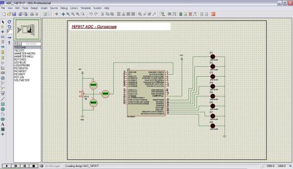
This is the circuit as shown on Proteus 7 simulation environment
The Gyroscope is replaced in simulation by a variable resistance because Proteus 7 does not contain a Gyroscope model.
Step 1: Software and Simulation
The code is written in C and compiled with Hitec C Compiler.
The program is very simple and straight forward. It starts by configuring the ports of the Microcontroller for input and output. Then the ADC Module is also configured ( Channel , sampling rate and result data format ).
Then the infinite loop of the program starts which contains the step of
starting the conversion ,
waiting for conversion to complete and
displaying the result on the LEDs.
When the circuit moves in clock wise direction , number of LEDs in one half of LEDs column illuminate according to the rate of change in angular motion.
And When the circuit moves in counter clock wise direction , the other half of the LEDs illuminate indicating change in direction and indicating rate of change in angular motion.
I added a software part that makes the buzzer sound in two different sound when the board is rotated to the Right or to the Left.
The Gyroscope is replaced in simulation by a variable resistance because Proteus 7 does not contain a Gyroscope model.
Here is part of the software used to convert the Analog output into Yaw direction and amplitude.
For more detail: PIC 16F917 Gyroscope interface
- What sensor is used to sense yaw rate?
The ADXRS613 yaw rate gyroscope from Analog Devices is used. - How is the gyroscope output read by the microcontroller?
The gyroscope analog output is read by the PIC16F917 ADC module. - How is direction indicated on the hardware?
LEDs on one half of the column light for clockwise rotation and the other half for counterclockwise. - Can the circuit be simulated in Proteus 7 with the actual gyroscope model?
No, Proteus 7 does not contain a gyroscope model; a variable resistor is used to emulate it in simulation. - What development tools are used to build the project?
The code is written in C and compiled with Hitec C Compiler and simulation is performed in Proteus 7. - What additional output does the software provide besides LEDs?
The software makes the buzzer sound in two different tones for rotation to the right or left. - What are the main software steps in the ADC loop?
Start the ADC conversion, wait for conversion to complete, and display the result on the LEDs. - How is the rate of rotation represented?
The number of illuminated LEDs corresponds to the rate of angular motion.
