


Summary of NOKIA3310 LCD PIC16F88 RESISTOR COLOR CODE CALCULATOR CIRCUIT
Summary: A simple resistor color-code calculator uses a PIC16F88 microcontroller with a Nokia 3310 LCD and a 4×3 keypad. Twelve keypad keys correspond to standard resistor colors. Users enter colors by row to form 3-, 4-, 5-, or 6-band resistors; the circuit validates allowed color positions, computes the resistance (0.1 Ω to 99 GΩ), and shows value on line 1 and tolerance on line 2 of the LCD.Parts used in the Resistor Code Calculator:
- PIC16F88 microcontroller
- Nokia 3310 LCD module
- 4 × 3 keypad (12 keys)
- Resistor color-coded input mapping (software mapping to keypad)
- Power supply (appropriate for PIC16F88 and LCD)
- Supporting passive components (decoupling capacitors, pull-ups)
- PCB or prototyping board and connectors
- Programming/debugging interface for PIC16F88
PIC16F88 Automates Four-Band Resistor Calculations
This project uses a PIC16F88 microcontroller to calculate the resistance and tolerance of standard four-band resistors automatically. A 4×3 keypad allows the user to enter resistor colors, while a Nokia 3310 LCD displays the selected bands and calculated result. The circuit can calculate values from 0.1 ohm up to 99 gigaohms according to the supported color combinations.
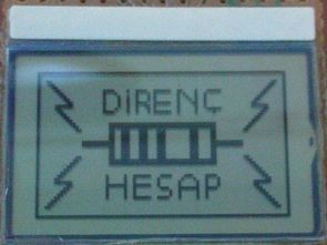
The practical benefit is that users do not need to manually remember multiplier values or calculate resistance from color bands each time. It also makes the project useful for learning how keypad input, embedded calculations, and graphical LCD output can work together in a microcontroller application.
Keypad Input Represents Resistor Band Colors
Each of the 12 keypad buttons corresponds to one resistor color: black, brown, red, orange, yellow, green, blue, violet, gray, white, gold, or silver. As colors are entered, the PIC16F88 stores them and displays them sequentially on the Nokia screen.
The firmware also prevents users from entering invalid combinations in certain band positions. For example, black, gold, and silver cannot be used for the first band, while only gold or silver can be selected for tolerance. This validation helps ensure that the displayed result follows the four-band resistor coding system.
Four-Band Resistor Values Are Calculated Digitally
In a four-band resistor, the first two colors represent significant digits, the third determines the multiplier, and the fourth defines tolerance. Gold represents ±5% tolerance, while silver represents ±10% in this project.
The microcontroller converts the keypad selections into these numerical values and formats the final resistance in ohms, kiloohms, megaohms, or gigaohms. This provides a practical example of how physical input data can be translated into meaningful engineering information through firmware.
PIC16F88 Controls the Complete Circuit
The PIC16F88 acts as the central controller for the keypad, display, and calculation logic. It operates using its internal 4MHz oscillator, which the project describes as providing 1 MIPS performance. The keypad is connected to PORTB in a 4×3 matrix arrangement, allowing multiple buttons to be read while using relatively few microcontroller pins.
Matrix scanning is a common embedded technique because the firmware activates keypad lines in sequence and checks which corresponding input is detected. This reduces the number of GPIO connections compared with wiring every button independently.
Nokia 3310 LCD Displays Inputs and Results
The Nokia 3310 LCD provides the user interface for the calculator. Entered resistor colors are shown on separate display lines, while the calculated resistance and tolerance are displayed at the top of the screen.
Using a graphical LCD instead of individual LEDs or seven-segment displays allows the project to show descriptive color names and formatted resistance values, making the output easier to understand during operation.
Power Supply Design Requires Voltage Consideration
The main circuit operates from a 5V DC supply, while the Nokia 3310 LCD requires a lower voltage. The project uses a resistor network to reduce the LCD supply voltage and series resistors between the PIC16F88 outputs and the LCD communication inputs.
The source also correctly notes an important limitation: a resistor divider is reliable as a power source only when the load current remains sufficiently predictable. Because the output voltage changes with load, the LCD supply should be measured during operation to confirm that it remains within the display's acceptable range. A dedicated regulator or suitable level-conversion solution can provide more controlled voltages where greater reliability is required.
Firmware Handles Keypad Scanning and Color Mapping
The software includes a function that scans the keypad matrix and assigns a numerical value to each detected key. Another function converts those numerical values into resistor color names such as Black, Brown, Red, and Gold for display on the LCD.
This separation between input scanning and display logic makes the firmware easier to understand because each function performs a specific task within the overall application.
Resistance Calculation Logic Uses the Multiplier Band
The direnc_hesap() function interprets the third resistor band and formats the result according to the appropriate resistance scale. Depending on the multiplier, the output is shown in ohms, kiloohms, megaohms, or gigaohms.
After calculating resistance, the same routine checks the fourth band and displays either 5% or 10% tolerance for gold and silver respectively.
PCB Design Completes the Standalone Calculator
The project also includes a dedicated printed circuit board layout. The PCB is designed for two-pin push buttons, while the Nokia 3310 display can be connected using standard 0.1-inch-spaced headers.
Moving from a schematic to a dedicated PCB turns the project into a more practical standalone tool and gives learners experience with both firmware development and physical electronic assembly.
Source: NOKIA3310 LCD PIC16F88 RESISTOR COLOR CODE CALCULATOR CIRCUIT
- What components make up the resistor code calculator?
The circuit uses a PIC16F88, a Nokia 3310 LCD, a 4×3 keypad, power supply, supporting passive components, PCB, and a programming interface. - Which keypad layout corresponds to resistor colors?
The 12 keys on the keypad correspond to black, brown, red, orange, yellow, green, blue, purple, gray, white, gold, and silver colors. - How many resistor band types can the circuit handle?
The application supports 3-, 4-, 5-, and 6-band resistor color codes. - What resistance range can be calculated?
Resistance values from 0.1 ohms up to 99 gigaohms can be calculated. - How are results shown on the display?
The calculated resistance value is printed on the first line of the LCD and the tolerance is shown on the second line. - Are invalid color entries prevented?
Yes; the circuit does not allow incorrect colors in wrong band positions per the rules described. - Which colors are not allowed in the first band?
Black, gold, and silver cannot be entered in the first band. - Which colors are not allowed in the second band?
Gold and silver cannot be entered in the second band. - What restriction exists for the tolerance band?
The tolerance band (fourth band for a 4-band code) may only be gold or silver in color.
Related projects
Exploring the PIC16F88 Microcontroller for Remote-Controlled Robotics
I. Design Summary The objective of this mechatronics system design project is to develop a straightforward control and interface platform for robotics...
Meters & Test Instruments · PIC16F688Determine capacitance by measuring the charging time using PIC16F688
When TEST botton is pressed, RA3 pin is set to "1". R2 and R3 are divide the voltage to 1/2 Vra3 which...
Beginner Tutorials · PIC16F1827Breadboard module for 18-pin PIC16F microcontrollers (PCB version)
Because of their compact size, ease of use and many built-in peripherals, the 18-pin PIC16F series processors (PIC16F628A, PIC16F88, and now PIC16F1827/47)...
Wireless & IoTExploring Various Applications of Microcontrollers: A World of Tiny Brains
Exploring Various Applications of Micro Controller Microcontrollers have become ubiquitous in the modern world with applications in nearly every industry. This student...
Wireless & IoTIntelligent Sips: Revolutionizing Dining with the SmartCup
Abstract The SmartCup Attachment is a comprehensive system designed for restaurants to monitor the liquid levels in their customers' cups. This system...
Wireless & IoTMaximizing Wi-Fi Capabilities with the Explorer 16 Development Board
As society progresses, the necessity for wireless communication is evolving from a mere luxury to an essential requirement. Wi-Fi, extending beyond conventional...

Muhammad Bilal
I am a highly skilled and motivated individual with a Master's degree in Computer Science. I have extensive experience in technical writing and a deep understanding of SEO practices.