Summary of Nixie Tube Ornament
This article details the creation of a Nixie Tube Ornament, a retro-inspired decoration featuring an IN-15A or IN-12 tube. The project integrates a 5V to 180V boost converter power supply, a KD155 tube driver IC, and a PIC microcontroller for control. It includes custom firmware and Eagle circuit board files, utilizing a socket carrier for easy tube replacement.
Parts used in the Nixie Tube Ornament:
- IN-15A symbol nixie tube
- IN-12 top view nixie tube
- High voltage power supply (Boost Converter)
- Tube carrier with IN-12 style socket
- KD155 nixie tube driver IC
- PIC microcontroller
- Induction coil
- Field Effect Transistor (FET)
- 5.1v zener diode
- Four wire interface
The Nixie Tube Ornament is a homage to the light-up&motion ornaments from the early 90’s. The ornament looks cool on a tree and makes a great gift. Finally, a use for IN-12/15 top view tubes!
I used an IN-15A symbol nixie in this ornament. An IN-12 works great too.
A video of the ornament alone:
A video of the ornament in my tree. (Yes, the walls are changing color. I have the si-light system in my apartment: http://si-light.sourceforge.net )
Details you will find in this instructable:
1. A small high voltage power supply that runs the tube.
2. A tube carrier to mount the nixie tube in a socket so it can be changed.
3. Firmware that runs the power supply and changes the digit displayed on the tube.
Everything you need to make your own nixie tube ornament is included in the project archive:
1. Circuit board in Eagle (Cadsoft).
2. Compiled firmware HEX file, and Mikrobasic source for the free (demo) Mikro compiler.
3. This instructable in .odt (Open Office) format.
Step 1: Design overview
The nixie tube ornament has 3 main parts:
1. A power supply – boosts 5 volts to 180 volts for the nixie tube.
2. A tube driver – changes the lighted tube digit by grounding one of the 10 tube cathodes. I used the Russian KD155-whatever.
3. A microcontroller – a PIC microcontroller ties everything together – it runs the power supply and changes the digits shown in the nixie tube through a four wire interface to the tube driver IC (see previous).
Step 2: Power supply (Boost Converter)
Nixie tubes are powered by a high voltage source (about 180 volts). To get this voltage we use a boost converter. An induction coil is abused pump-like to fashion 180 volts from 5 volts. Cool. Everything I know about boost converters can be found in this instructable [http://www.instructables.com/id/EHF3DSER24EP286HG8/].
The actual power supply design is taken from my attempt at a nixie watch, see it here [http://www.instructables.com/id/EMR0RL7C56EP2877RA/]. The main difference between this supply and the reference supply in the boost converter instructable is a reduction of components. There are no indicator lights, no large expensive filter caps, and only one input cap. Since the ornament is a single tube, dropping a few capacitors has no functional impact.
I also dropped supply voltage calibration. In the reference design the PIC measures the input voltage and calculates the ideal charge and discharge time for the inductor given the inductor size (mA) and value (uH). I just calculated the charge/fall time for the coil based on a 6 volt supply and hard-coded these values (worst case scenario with 4 AA batteries, though I use NiMH). If the supply is lower (as with my NiMH) the coil is not being used to its full potential, but it doesn’t matter because we only need a few mA of HV for a single tube. Sweet. And we saved 2 more resistors. More than 6V will probably cause over heating in the inductor/FET.
Note: There is a 5.1v zener with 1 ohm resistor to protect the uC if the supply is > 5 volts, but this isn’t a problem with NiMH or a wall-wort
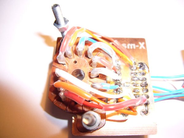
Step 3: Tube carrier
The ‘tube carrier’ is the face of the ornament It holds an IN-12 style nixie tube socket and the KD155 nixie tube driver IC. I cut the circuit board to fit around the nixie tube socket and screwed the socket to the board. Long screws were used so that the power supply could be bolted to the back.
Assembly was a bit intense. Wires from the IC to the nixie tube socket were soldered directly into the same hole as the IC. Not a great design, but it worked and saved a lot of space. The leads connecting to the tube socket were covered with shrink tube for a more professional look (but mostly to protect against shorts).
Step 4: Firmware
The firmware is really simple:
1. First, values for the power supply are loaded into the pulse width modulator registers.
2. All the ports, timers, and what-not get setup.
4. Timer 1 is setup with maximum pre&post scalers, on interrupt the nixie digit is changed.
3. The firmware then enters an endless loop of measuring the output voltage and applying pulses to the FET.
For more detail: Nixie Tube Ornament
- Which nixie tubes work best for this ornament?
An IN-15A symbol nixie is used, but an IN-12 works great too. - How does the power supply generate high voltage?
It uses a boost converter that abuses an induction coil to fashion 180 volts from 5 volts. - What components make up the main design overview?
The three main parts are a power supply, a tube driver, and a microcontroller. - Can I use NiMH batteries instead of AA batteries?
Yes, the author uses NiMH batteries despite calculating values based on a worst-case scenario of 4 AA batteries. - Does the design include indicator lights or large filter capacitors?
No, the design drops these components to reduce the part count without impacting functionality. - How is the firmware configured to change digits?
Timer 1 is set up so that on interrupt, the nixie digit is changed within an endless loop measuring output voltage. - What software tools are included in the project archive?
The archive includes a circuit board in Eagle, compiled firmware HEX files, and Mikrobasic source code. - Why was supply voltage calibration dropped from the reference design?
Calibration was removed because only a few mA of HV are needed for a single tube, saving resistors and simplifying the code.