Summary of Mini PIC Dev Board using PIC18F452
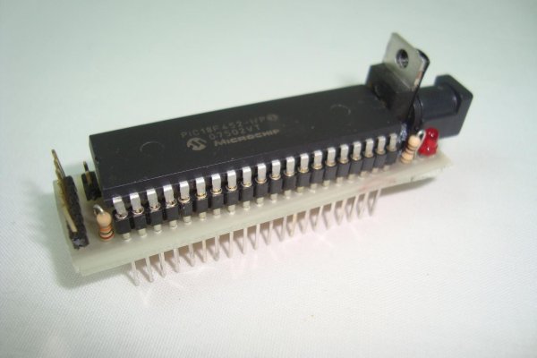
This article details the design of a compact mini development board for PIC 18F452 microcontrollers, enabling easy breadboard integration with built-in power and programming circuits. The project aims to eliminate repetitive circuit building by providing a reusable platform powered via a 9V jack or battery, regulated to 5V, and programmable via ICSP using a PICKit programmer.
Parts used in the Mini PIC Dev Board:
- PIC 18F452
- PICkit Programmer
- LM7805 +5v Regulator
- 2x 10uF Capacitors
- Vertical Header Pins
- 10kΩ Resistor
- 330Ω Resistor
- Power Jack
- 2x Red LED
- 20 MHz Crystal
- Breadboard
- Breadboard Wire
- SIPs
- 9v Power Jack Connector
- Battery Holder
- PC Board
- Ferric Chloride (Etchant)
For one reason or another I really like to use breadboards for building prototype designs. The breadboard offers superior flexibility in that you can change a single electrical connection at any time, as long as you have a long enough wire. One of the draw backs of the breadboard is that you tend to build the same circuits over and over again.
Since I like to use the PIC microcontroller in my projects I figured it would be nice to make a mini development board that could fit onto a breadboard and already had a power circuit and programming circuit connected. This way I won’t have to rebuild the same power + programming circuit every time I start a new project. This article describes my design process so that you can build one too!
Purpose & Overview of this project
The goal of this project is to build a development board for any of the PIC 18F 40 pin series so that it can be powered up, programmed and used while also connected to a bread board. Since I plan to use the development board connected to a breadboard the PCB layout needs to be as compact as possible.
I will design this board around the PIC 18F452 microcontroller, the LM7805 +5v regulator to provide power and a standard 6 pin header to connect any ICSP connector to the board and program the PIC. A standard power jack should be used so a normal “wall-wart” transformer can be used to power this dev board.
PICkit Programmer
LM7805 +5v Regulator
2x 10uF Capacitors
Vertical Header Pins
10kΩ Resistor
330Ω Resistor
Power Jack
2x Red LED
20 MHz Crystal
Breadboard
Breadboard Wire
SIPs
9v Power Jack Connector
Battery Holder
PC Board
Ferric Chloride (Etchant)
Parts List Details
To make things more clear, I’ll describe the more important parts from the list above, in detail below. This way there’s no confusion about what it’s role in this project is.
PIC 18F452
The microcontroller that this PC board is designed for is the PIC 18F452, but realistically an 18F, 40 pin PIC can be used since the family shares a common power, ground and programming pinout.
PICKit Programmer
The 6 pin programming header will conform to the ICSP header standard so that we can use a PICKit2 or PICKit3 to program the PIC.
LM7805 +5v Regulator
Since the 18F452 is a +5v part, we will use a +5v regualtor, the famous LM7805. This part takes your input voltage, for example +9v and turns it into a +5v output.
Vertical Header Pins
The vertical header pins will be used to build the ICSP connection for programming the PIC. Also, a small 2 pin jumper will be available to connected the PGM pin, for low-voltage programming, even though I doubt I’ll ever use that option.
Ferric Chloride
This is the etchant used to eat away the copper from the PC Board that we don’t want, leaving behind only our layout design to solder all the parts to.
Copper Clad PC Board
This is the type of PCB that we will use to build our circuit. Copper Clad is the most common and also the cheapest option for building an electric PC Board.
9v Power Jack Connector
Since I like using rechargeable batteries with my project, I’ll use a +9v to Power Jack connector to provide power. You could alternatively use a “wall-wart” transformer and the system will work the same.
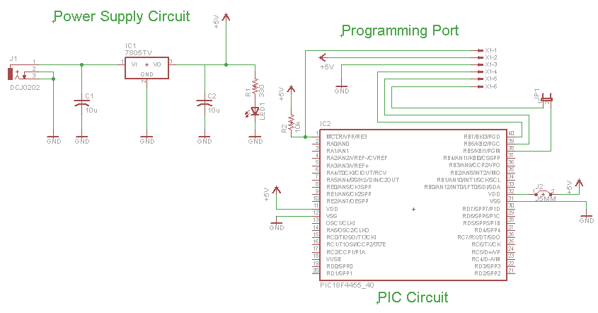
Schematic Overview
The schematic for this project is kept to be as simple as possible. There are definitely ways you could add more parts to build a more redunant power and programming port, but that would increase the size of the PCB, we’re going for compact, yet functional here. The main parts in the schematic are the PIC 18F452, LM7805 and Power LED.
Schematic Specifics
Power Regulator
The 7805 converts the input +9v down to a +5v output which powers the PIC. The PIC has two spots where it connects to power and ground, and there is a single 10kΩ resistor connected to the MCLR Pin1 of the pic that goes to power.
ICSP connection
ICSP is short for in-circuit serial programmer and this is the port used on almost every PIC microcontroller to load your program onto it. The PICKit3/PICKit2 have the same pinout as the connector seen above, the little dot on the PICKit3/PICKit2 tells you which connection is PIN1 or MCLR.
For more detail: Mini PIC Dev Board using PIC18F452
- What is the primary purpose of this project?
The goal is to build a compact development board for PIC 18F 40 pin series that can be powered, programmed, and used while connected to a breadboard. - Which microcontroller is the board designed around?
The board is designed around the PIC 18F452, though any 40-pin PIC from the 18F family can be used due to shared pinouts. - How does the LM7805 function in this circuit?
The LM7805 converts an input voltage like +9v down to a stable +5v output required to power the PIC. - Can I use a wall-wart transformer instead of a battery?
Yes, you can use a normal wall-wart transformer with the standard power jack, and the system will work the same as with rechargeable batteries. - What type of programmer is compatible with the 6 pin header?
The 6 pin programming header conforms to the ICSP standard, allowing the use of a PICKit2 or PICKit3. - What role does Ferric Chloride play in the build process?
Ferric Chloride is the etchant used to remove unwanted copper from the PC Board, leaving only the desired layout design. - Why are vertical header pins included on the board?
Vertical header pins are used to build the ICSP connection for programming, and they also allow for a small jumper to connect the PGM pin for low-voltage programming. - Is there a resistor connected to the MCLR Pin?
Yes, there is a single 10kΩ resistor connected to the MCLR Pin1 of the PIC that goes to power.