We are now in the fourth part of the microcontroller tutorial. We have a microcontroller circuit diagram ready. It’s time to make a circuit board. I love this part. This is the “magical” step that takes the idea we started with and turns it into something real.
But let’s recap. So far we have learned:
- Part 1: What is a microcontroller?
- Part 2: How to choose your microcontroller?
- Part 3: How to design a circuit diagram for your microcontroller?
 In this fourth part, we are going to create a circuit board for our circuit, then get this board created in one way or another. This can be done in several ways, as we’ll see later.
To design our circuit board we’ll use Cadsoft Eagle. It’s available in a free version and works on Windows, Mac and Linux.
Designing Schematics For Our Microcontroller Circuit
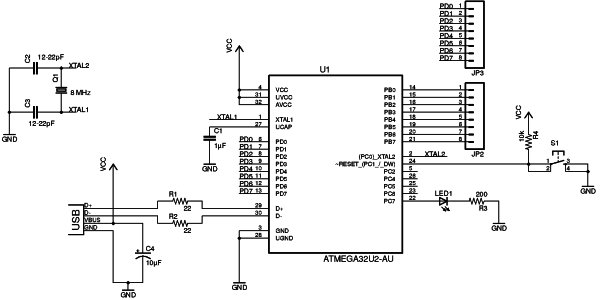
The first thing we need to do, is to put our schematic design into Eagle’s schematic editor. If you are not familiar with this process, check this out: How to create schematics with Eagle
In the previous part of this microcontroller tutorial, we decided on which components to use and how to connect them.
The ATmega32U2 microcontroller, is not in Eagle’s default library. I could have designed my own custom component, but to save time I used a library that I found here: https://github.com/civanovici/roduino/tree/master/eagle/eagleLibrary
For the USB connector, I used one from Sparkfun’s library here: https://github.com/sparkfun/SparkFun-Eagle-Libraries
Designing Out Board Layout
The next step is to design the board.
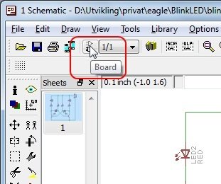
In Eagle, we can click on the «Board» button in the toolbar to open the design editor. If no board design exists for your schematics, you will be asked if you want to create one. Answer «Yes» to this.
 I always start out by defining my board size. I know that I can get really cheap prototypes if I stick to 5cm x 5cm (1.9685 in x 1.9685 in), so I will set my board size to this.
Now it’s time to place the components onto the board and draw the connections.
In this design, I wanted to draw only on one side, so that it would be easier to mill or etch the board – just in case I wanted to do this.
For more detail: Microcontroller Tutorial 4/5: Creating a Microcontroller Circuit Board