Summary of µ-Wire – USB on an ATtiny 10
Atmels ATtiny10 (SOT23, 1KB flash, 32B SRAM) was used to implement a USB-compatible little-wire subset to control a single WS2812 LED via USB using exactly three free I/O pins. The project retained protocol compatibility with little-wire host programs, enabling use as an RGB indicator. The ATtiny10 plus a few discrete components and connectors form an extremely compact USB-controllable WS2812 driver.
Parts used in the µ-Wire: USB on an ATtiny10:
- Atmel ATtiny10 (SOT23, 6-pin)
- WS2812 LED (single RGB LED)
- USB connector
- Decoupling capacitor(s)
- Zener diode(s)
- Resistor(s)
- PCB with rear-side discrete components
Atmels AVR ATtiny10 are surprisingly powerful devices that come in an extremely tiny SOT23 package with only 6 pins. The have 1kb of flash, 32 bytes of SRAM and use the reduced AVR core which only supports 16 instead of 32 register. It seems like Atmels idea of these devices is to use them as an advanced blinker, and to replace tiny logic circuits. But other people have shown that much more is possible. For example the noiseplug (video), a chiptune player, and a Simon Says game.
I previously used the ATtiny10 in the TinyTouchbutton, a touchbutton controlled light with WS2812 LEDs. This time I aimed higher: Is it possible to turn the ATtiny10 into a USB compatible device? My goal was to implement a subset of the little-wire functionality, to control a WS2812 LED by USB. This takes 3 I/O lines, which is exactly the number of free pins on the ATtiny10.
Littlewire supports several functions to control WS2812 LEDs on arbitrary I/O ports. I simplified this to only supporting a single LED on a specific pin, however still retained protocol compatibility. This means that all the little-wire host-programs still work. The finished device can, for example, be used as an RGB indicator LED similar to the Blink(1).
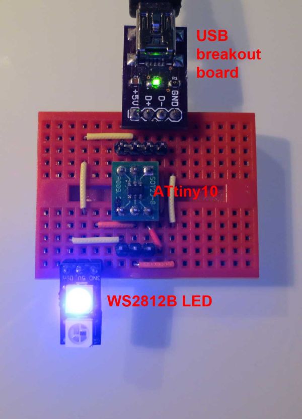
My test setup is shown below. The ATtiny10 is almost the smallest part of the circuit. There are some discrete components on the rear-side of all PCBs, so do not be surprised about missing decoupling capacitors, zener diodes and resistors.
For more detail: µ-Wire – USB on an ATtiny 10
- Can an ATtiny10 be used as a USB device?
Yes; the project implements a USB-compatible device on an ATtiny10 by providing a subset of little-wire functionality. - What functionality was implemented on the ATtiny10?
A subset of little-wire functionality sufficient to control a single WS2812 LED while retaining protocol compatibility. - How many I/O lines are needed to control the WS2812 LED?
Three I/O lines are required, which matches the number of free pins on the ATtiny10 in this project. - Does the device remain compatible with existing little-wire host programs?
Yes; protocol compatibility was retained so existing little-wire host programs still work. - What is the intended usage of the finished device?
The finished device can be used as an RGB indicator LED similar to the Blink(1). - Are there additional components beyond the ATtiny10 on the PCB?
Yes; there are discrete components on the rear side, including decoupling capacitors, zener diodes, and resistors.