Summary of Lab Test Bench-oscilloscope/waveform
This project outlines the development of a low-cost, open-source digital oscilloscope and waveform generator using a chipKIT WF32 board. The author aims to create a versatile lab bench tool that is easily reproducible by students and engineers. Currently, the hardware setup successfully connects peripherals via SPI, allowing the DAC to generate signals and the ADC to capture them for display on a computer. While the core functionality is operational, advanced features like an LCD interface and rotary encoder are planned for future phases.
Parts used in the Lab Test Bench:
- chipKIT WF32
- USB A to micro B cable
- Wires
- PmodAD1
- Pmod-DA1
- PmodENC - Rotary encoder (planned)
- LCD-128x64 (planned)
- 4x4 Matrix Keypad (planned)
Lab test bench
For electrical engineering classes, basic lab equipment such as oscilloscopes and signal generators usually cost hundreds of dollars.
In this project I want to implement the hardware and initial software for a small, affordable digital oscilloscope and waveform generator based off an chipKIT board.
This is my Bachelor project/thesis and my main goal is to create a low-cost oscilloscope/waveform generator/impedancemeter/powermeter/spectrum analyzer that could be easily reproduced using the documentation related to this project.
The parts are generic, ensuring anyone who want to build this project, easy access to all electronic components.
This project is not finished!!!
Only few features were implemented!!!
Youtube about this project:
Parts needed:
-chipKIT WF32 http://www.digilentinc.com/Products/Detail.cfm?Nav…
-USB A to micro B cable
-Wires
-PmodAD1 http://www.digilentinc.com/Products/Detail.cfm?Nav…
-Pmod-DA1 http://www.digilentinc.com/Products/Detail.cfm?Nav…
parts needed for the next phases of the project:
-PmodENC – Rotary encoder http://www.digilentinc.com/Products/Detail.cfm?Nav…
-LCD-128×64
-4×4 Matrix Keypad
Current status:
-I have successfully connected to the WF32 all peripherals used except the LCD;
-I established communication with the computer;
-I can use in parallel the ADC and DAC mudules;
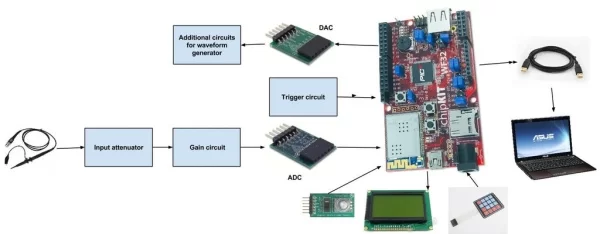
In the next application the DAC module generates a sinusoidal signal and the ADC module picks up the signal and sends information to the computer via serial interface.
The data sent to the computer is taken by a specialized software which display it as a waveform.
Software needed for this application:
-MPIDE-http://chipkit.net/started/install-chipkit-softwar…
instalation guide-http://chipkit.net/started/install-chipkit-softwar…
-Oscilloscope software-http://www.x-io.co.uk/serial-oscilloscope/
-ADC module library from Digilent –http://www.digilentinc.com/Products/Detail.cfm?Nav…
*In the bottom of the page you will find a Download link to MPIDE library of ADC module
-DAC module library from Digilent-http://www.digilentinc.com/Products/Detail.cfm?Nav…
*same way as for the ADC
*Inside the .zip files you will find instructions about how to install libraries.
STEP 1: MPIDE Project
After instaling the libraries.
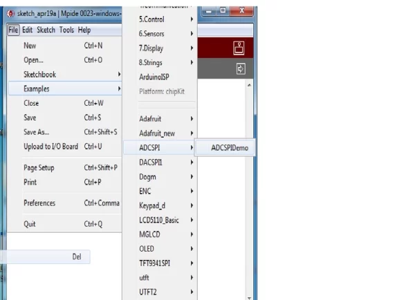
Start MPIDE, go to FILE-Examples>ADCSPI>ADCSPIDemo
Now you have loaded the ADC demo example.
Next we will load the DAC example.
go to FILE-Examples>DACSPI1>DACSPI1Demo
Now you can test them separately, if you want to do so, you will have to connect them as follows.
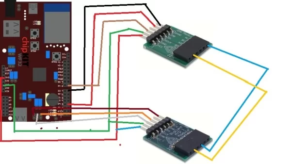
On the board we will connect the PMODS to J10 Connector(see image 3)
PMODAD1 WF32
CS(pin1) ———-> SS2, pin 5
Pin2(Data 1) ———–> Not connected
Pin3 (Data 2) ———–> MISO( pin 1)
Pin 4(SCLK) —————> SCK2(pin3)
Pin(GND) —————–> GND(pin 6)
Pin 6 (vcc)—————> 3V3(board)
PMODDA1 WF32
CS(pin1) ———-> SS2,
pin 5 Pin2(Data 1) ———–> MOSI(pin4)
Pin3 (Data 2) ———–> Not connected
Pin 4(SCLK) —————> SCK2(pin3)
Pin5(GND) —————–> GND(pin 6)
Pin 6 (vcc)—————> 3V3(board)
In the next step we will test the modules the same time, and we will connect the ADC input to DAC output.
STEP 2: Using Two Spi Modules-oscilloscope and Waveform Generator
In this step we will use both Pmods, to do so we will have to open one of the examples for Pmods( ADC or DAC) and to add the library of the other.
In this project I chose to use SPI1 for DAC and SPI0 for ADC
See the connections in the image.
SPI1: Synchronous serial port. This is an additional SPI interface on the PIC32 microcontroller that can be assessed
using the DSPI1 object from the DSPI standard library. It is not accessible using the SPI standard library. Several of the SPI1 signals are shared in various ways with other peripheral functions. SS1 is connected to connector J9, pin 15, the connector location for digital pin 7, via a 1K ohm resistor. This signal is accessed via digital pin number 71. SDO1 is accessed via digital pin 3. This conflicts with one of the PWM outputs accessed using analogWrite(). SDI1 is accessed via digital pin 38. SCK1 is connected to connector J7, pin 1, the connector location for digital pin 8, via a 1K ohm resistor. This conflicts with external interrupt INT3. This signal can be accessed via digital pin number 72
You can add a certain library in a existing project or a new project from: sketch>import library.
and just paste the fallowing code:
#include<ADCSPI.h>
#include<DACSPI1.h>
#include<DSPI.h>
DACSPI1 myDACSPI1; // the library object
float dMaxValue = 3;
float dMinValue = 0;
float dStep = 0.005;
float dValue;
ADCSPI myADCSPI; // the library object
unsigned int wValue; // unsigned 16 bit variable to store integer value
float fValue; // float variable to store physical value
char sMsg[100]; // character string to keep message that is displayed on serial monitor
void setup()
{
//Create a connection to display the data on the serial monitor.
Serial.begin(9600); // initialize PmodDACSPI1 on SPI
myADCSPI.begin(PAR_ACCESS_SPI0); // corresponds to DSPI0 – connector JB myDACSPI1.begin(PAR_ACCESS_SPI1); // corresponds to DSPI1 – connector J1
}
void loop()
{
// increase physical value from minimum to maximum value
for(dValue = dMinValue; dValue <= dMaxValue; dValue += dStep)
{
// send value to the DA converter
myDACSPI1.WritePhysicalValue(dValue);
delay(20);
// wait some time
fValue = myADCSPI.GetPhysicalValue()*15; // read physical value
sprintf(sMsg, “%f\r”,fValue); // format text to be displayed
Serial.println(sMsg);
// display text on serial monitor
delay(20);
}
// decrease physical value from maximum to minimum value
for(dValue = dMaxValue; dValue >= dMinValue; dValue -= dStep)
{
// send value to the DA converter
myDACSPI1.WritePhysicalValue(dValue);
delay(20); // wait some time
fValue = myADCSPI.GetPhysicalValue()*15; // read physical value
sprintf(sMsg, “%f\r”,fValue); // format text to be displayed
Serial.println(sMsg); // display text on serial monitor
delay(20);
}
}
After you pasted the code, you program the board: and you have to start the Serial Osciloscope software.
In this short movie at minute 1:55 you can see how to use Serial Osciloscope software
Source: Lab Test Bench-oscilloscope/waveform
- What is the main goal of this project?
The goal is to create a low-cost, easily reproducible digital oscilloscope, waveform generator, and other measurement tools using generic electronic components. - How can I connect the PmodAD1 to the WF32 board?
Connect CS to SS2 pin 5, Data 2 to MISO pin 1, SCLK to SCK2 pin 3, GND to GND pin 6, and VCC to 3V3 board pin 6. - Can the ADC and DAC modules be used in parallel?
Yes, the project establishes communication where both modules operate simultaneously to generate and pick up signals. - Which software is needed to display the waveform data?
You need MPIDE for programming and the Serial Oscilloscope software from x-io.co.uk to visualize the data sent via the serial interface. - Does the project currently include an LCD display?
No, the current status indicates that the LCD has not yet been connected or implemented. - What libraries must be imported for the combined ADC and DAC code?
The code requires importing the ADCSPI library, the DACSPI1 library, and the DSPI library. - How does the system send data to the computer?
The ADC module reads the signal and sends information to the computer via a serial interface at 9600 baud rate. - Are the electronic components generic and accessible?
Yes, the parts listed are generic to ensure easy access for anyone wishing to build the project.