Summary of Interfacing LCD and Keypad with PIC16F877A Microcontroller
This tutorial explains interfacing a 16×2 LCD and a 4×3 keypad with a PIC microcontroller to create an embedded system. It details the LCD's Data and Command registers, control pin operations (RS, EN, R/W), and the polling method used to scan the keypad rows and columns for input before displaying it on the screen.
Parts used in the PIC Microcontroller Interfacing Project:
- PIC Microcontroller
- 16×2 LCD
- Data Register
- Command Register
- Register Select (RS) Pin
- Enable (EN) Pin
- Read/Write (R/W) Pin
- 4×3 Keypad
- Row Pins
- Column Pins
Interfacing LCD and Keypad are one of the important interfacing concepts of PIC microcontroller since both the input and output element can form a complete embedded system design. This tutorial is about teaching you how to get input input values from keypad by polling method and display the input into a 16×2 LCD.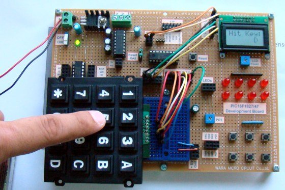
16×2 LCD:
This type of LCD is widely used to display the status of the system and to display the obtain output. This LCD consists of 16 columns and 2 rows, therefore named as 16×2 LCD. Usually a LCD consists of two built in registers known as Data and Command register. Command reg is meant for giving commands such as blink on, cursor on/off etc while Data reg is to display the input character.
You have to follow these steps to write a command or data into the LCD.
- Place the Data/Command in the pins D0-D7 of the LCD.
- If you are intended to write command you gotta make the RS(register select) pin of the LCD low, that is RS=0
- Whereas for writing data you have to make this RS high, that is RS=1
- Then the EN of the LCD must undergo a high to low logic transition with some delay in between them, that is EN=1 to EN=0 with specific delay.
- The R/W pin should remain in the Logic 0.
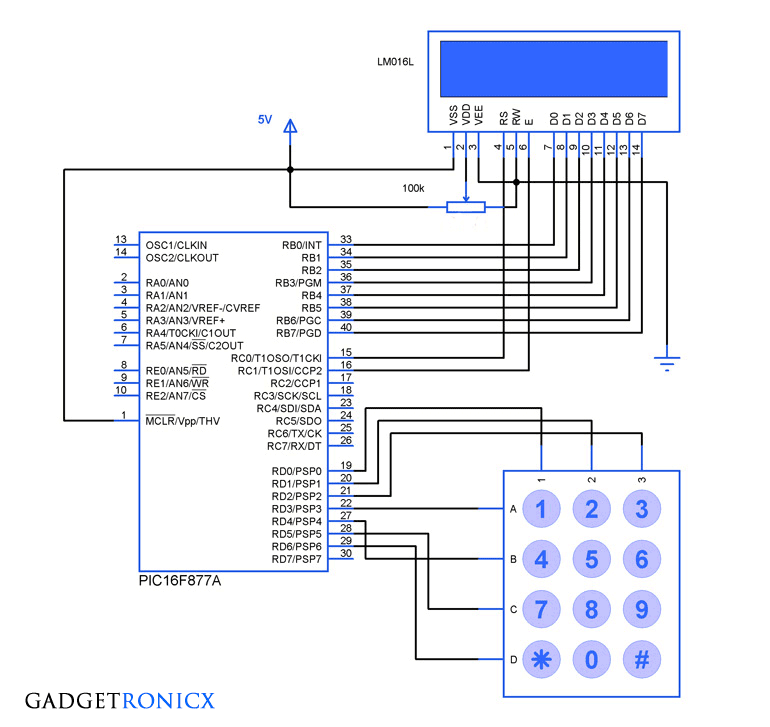
4×3 Keypad:
We have used a 4×3 keypad which means it has four rows and three columns in it. The keypad was scanned for any key inputs and this was done by means of a method called polling. The scanning takes place by keeping a specific Row low at a time and read the status of the column pins as input at that instant. This chain goes on through all the rows and by this way input is read by Microcontroller.
For more detail: Interfacing LCD and Keypad with PIC16F877A Microcontroller
- What is the primary purpose of this tutorial?
To teach how to get input values from a keypad by polling and display them on a 16×2 LCD using a PIC microcontroller. - How does the 16×2 LCD function regarding its registers?
It uses a Data register to display input characters and a Command register for commands like cursor control. - What value must the RS pin have to write a command?
The RS pin must be low, meaning RS equals 0. - What logic transition is required for the EN pin during data writing?
The EN pin must undergo a high to low logic transition with specific delays between them. - What state should the R/W pin remain in during operation?
The R/W pin should remain in Logic 0. - How is the 4×3 keypad scanned for inputs?
It is scanned using a polling method that keeps a specific row low at a time while reading column pins. - What components form the complete embedded system design mentioned?
An input element (keypad) and an output element (LCD) connected to a PIC microcontroller.