


Summary of Interfacing DS1307 Real time clock with PIC16f877
The article explains interfacing a DS1307 real-time clock (RTC) with a PIC16F877 microcontroller via I2C. It describes DS1307 features (BCD clock/calendar, 56 bytes NV SRAM, automatic month/leap-year adjustment, I2C slave) and outlines reading BCD-formatted time from the DS1307, converting BCD nibbles to ASCII digits, and displaying the result on an LCD. Sample conversions for higher and lower nibbles are given.Parts used in the Interfacing DS1307 with PIC16F877 Project:
- DS1307 Real Time Clock IC
- PIC16F877 microcontroller
- 16x2 LCD display (or compatible LCD)
- I2C pull-up resistors (typically for SDA and SCL)
- Crystal/resonator for DS1307 (32.768 kHz)
- Backup battery for DS1307
- Power supply (VCC and GND connections)
- Connecting wires and PCB or breadboard
In any advance project we need real time clock synchronize with our work and for this purpose the best option is DS1307 (RTC Ic). Interfacing DS1307 Real time clock with PIC16f877 is done by I2C communication. To know I2C protocol you may refer my previous post “Interfacing external EEPROM with PIC Microcontroller”. To know about Interfacing DS1307 Real time clock with PIC16f877, we should know something about DS1307 IC.
Real time clock ( DS1307):
The DS1307 serial real-time clock (RTC) is a low-power, full binary-coded decimal (BCD) clock/calendar plus 56 bytes of NV SRAM. Address and data are transferred serially through an I2C, bidirectional bus. The clock/calendar provides seconds, minutes, hours, day, date, month, and year information. The date at the end of the month is automatically adjusted for months with fewer than 31 days, including corrections for leap year. The DS1307 operates as a slave device on the I2C bus. Access is obtained by implementing a START condition and providing a device identification code followed by a register address. Subsequent registers can be accessed sequentially until a STOP condition is executed.
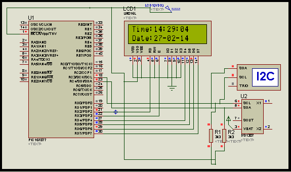
Project Description:
In this project we will see how we interfaced DS1307 with pic16f877 via I2C protocol. After interfacing DS1307 we recive the data from DS1307 and display it on LCD. Weall ready know before that DS1307 is send data in full BCD format. So we have to convert this data in digit and send to display on LCD.
Now question is how we convert BCD number to 4 bit number?
For getting higher nibble we use command
return ((bcd >> 4) + ‘0’) : it means the number will be Binary Right Shift 4 times with loading zero on left side.
For getting Lower nibble we use command
return ((bcd & 0x0F) + ‘0’) : it means we did and operation 0F with BCD number.
For more detail: Interfacing DS1307 Real time clock with PIC16f877
- What communication protocol is used to interface DS1307 with PIC16F877?
The DS1307 is interfaced using the I2C protocol as described in the article. - What data format does DS1307 send for time and date?
DS1307 sends clock and calendar data in full BCD (binary-coded decimal) format. - How do you obtain the higher nibble from a BCD byte?
Get the higher nibble by right shifting the BCD byte by 4 and adding the ASCII zero: (bcd >> 4) + '0'. - How do you obtain the lower nibble from a BCD byte?
Get the lower nibble by masking with 0x0F and adding the ASCII zero: (bcd & 0x0F) + '0'. - Does the DS1307 adjust for month lengths and leap years?
Yes, the DS1307 automatically adjusts the date for months with fewer than 31 days and includes leap year corrections. - How is access to DS1307 registers obtained on the I2C bus?
Access uses a START condition followed by the device identification code and a register address; registers can then be read sequentially until a STOP is issued. - Can the DS1307 act as an I2C master?
No, the DS1307 operates as a slave device on the I2C bus. - What additional memory does the DS1307 provide?
The DS1307 provides 56 bytes of nonvolatile SRAM.
Related projects
PIC16F877 Driving LCD in 4-Bit Mode using PIC16F877 with Proteus Simulation
Introduction This microcontroller project shows how a PIC16F877 can drive an LCD display using 4-bit mode inside a Proteus simulation.The project demonstrates...
Programmers & ICSP · PIC16F877AEPE PIC/LCD Demo using PIC16F877 with Proteus Simulation
IntroductionThe EPE PIC/LCD Demo is a classic microcontroller project that demonstrates how a PIC16F877 can fully control a PG12864F graphical LCD.Designed as...
Motors & Robotics · PIC16F877AEfficient Sun-Following Robot: A Solar Tracker with Microcontroller Control
Abstract The impending global challenge of dwindling non-renewable fuel resources underscores the urgency of transitioning towards renewable energy alternatives like solar power....
Communication & Interfacing · PIC18F4520CAN FD Node based on a PIC18 Microcontroller
The introduction sets the stage for an embedded systems project that involves developing a Embedded C CAN FD project using the MCP2517FD...
Communication & InterfacingLAN9662 Gigabit Switch: Optimized for Industrial Ethernet
Introduction It should come as little surprise therefore that one element of what is now more commonly referred to in some circles...
Communication & InterfacingPIC Microcontroller: Fundamentals & Applications for Students
Introduction Microcontrollers are the key components in the embedded systems market. A variety of embedded systems was formed and developed after the...

Ibrar Ayyub
I am an experienced technical writer holding a Master's degree in computer science from BZU Multan, Pakistan University. With a background spanning various industries, particularly in home automation and engineering, I have honed my skills in crafting clear and concise content. Proficient in leveraging infographics and diagrams, I strive to simplify complex concepts for readers. My strength lies in thorough...