Summary of Interactive LED Beer Pong Table 2.0 (BPT X5)
This article details the construction of an interactive LED Beer Pong Table 2.0, emphasizing customizable electronics and a smaller 2'x8' footprint. It covers three kit options (Fully Assembled, Unassembled, PCB Only) and guides users through assembling the master PCB, RGB pods, LED rings, and a central LED grid. The project integrates features like air baths for cleaning balls, VU meters, Bluetooth connectivity, SD card storage for custom animations, and IR remote control, requiring varying levels of soldering and woodworking skills depending on the chosen kit.
Parts used in the Interactive LED Beer Pong Table 2.0:
- Master PCB
- 20 RGB Pod PCBs
- 120 RGB 5050 SMD LEDs
- 384 LEDs for the 32x12 Grid
- 12 LED Rings
- Air Bath Fan and Sensors
- VU Meter Module
- Bluetooth Module
- Micro-SD Card
- 16x2 LCD Display
- IR Receiver and Remote
- EEPROM Chip
- Plywood and Acrylic Sheet
- Hinge and Braces
- IDC Cables and Connectors
The nice thing about building one of these tables from a kit is that the more difficult parts of the project have been completed (Electronic Design, PCBs made, etc.) but more importantly, you can fully customize the table to your liking. The photos that I posted above are of the version that I created, but you can completely change the layout of your table. Add more LEDs to the unused PWM channels, maybe you’ll switch out the LED rings for small LED signs/logos, completely omit the LED grid and just add LED strips, etc etc. There are a lot of extra PWM channels that aren’t aren’t in use on the master PCB and can be put to use!
If you do plan to swap out certain LED modules (like the LED rings), you must take care not to exceed the maximum ratings of the transistors that are driving those devices. This is all listed in detail later in the Instructable. For now, just take a moment to come up with a new layout for the wickedest beer pong table this world has ever seen. Once you’re done that, continue through the Instructable and assemble it!
Note
The source code, CAD files, schematics and bill of materials are all included in the downloadable zip file in this step.
Step 2: Preparation: Project Overview
Version 2.0 of the beer pong table has many added features that the original table never had. On top of that, this Instructable will show how to build a 2’x8′ table instead of the 3’x8′ size of the first table (I did this as I wanted to create a table with a smaller footprint. I.e. less space needed for it and cheaper to ship). You will also notice that the PCBs and wiring is completely encased inside of the table, whereas the other table j
ust had an open bottom.
This new table has 1122 total LEDs on it, it is capable of controlling up to 608 individual channels (96 of which are capable of 16-bit PWM), it only has one master PCB and the 20 RGB pod PCBs, it can read and write to an SD card, it has a 16×2 LCD display, an IR receiver built into the table so that it can be controlled with a remote, a breakout connector for VU meter capabilities, a bluetooth module and a couple more features. The breakdown of the features are listed below.
LED Grid
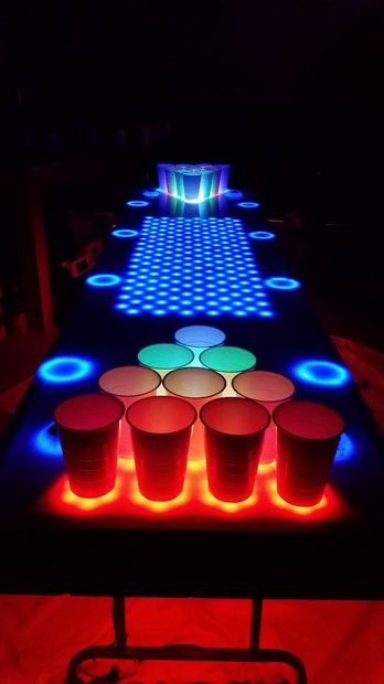
In the center of the table we can create any animation that will fit into a 32×12 pixel grid. We are able to display scrolling text across it, watch a pong animation, display a sine wave, display the score of the game, etc. There is a huge amount of possibilities! Since we are able to detect when a cup is removed from the table we can make specific animations that trigger exactly when that happens. We’ll get more in-depth with that later. The table actually supports a maximum display size of 32×16, however I have made it only 32×12 to span further across the table.
20x RGB Pods w/ Infrared Sensors
At each end of the table you will see 10 pods. The 16oz cups that are used for beer pong are placed over top of these pods. Each pod contains 6 RGB LEDs and 1 infrared sensor and we are able to light up the pods with any color that we would like. The infrared sensor will detect whether or not a cup is over top of the pod, so if a cup is removed we can change the color of the pod, begin an animation on the LED grid, run an animation on the RGB pods, etc.
Air Baths
There is an air bath on each side of the table. The purpose of the air bathes are to blow any debris off of the ping pong balls, thus cleaning them. When a player drops a ball to their left into the “IN” hole of the air bath, it detects the ball and starts a fan. This fan will move the ball down a pipe, removing debris and blowing it out the “OUT” hole to the right of the player. The player then grabs the ball and the air bath shuts off. Players can also dunk the ping pong balls in a cup of water before putting them into the air bath to get a better clean.
LED Rings
There are a total of 12 LED rings on the beer pong table. The outer edges of the table contain 4 LED rings each and the air baths make up the other 4. Much like the 32×12 LED grid, the LED rings are just used for animations. They can be set to go in accordance with music (VU Meter feature must be turned on), fade in and out, flash rapidly or any other cool animation that you can think of. Beer cups can be set inside of the LED rings on the railing which provides a cool effect on the upper lip of the cup. This table can support up to 16 LED rings on the specified PWM channels and the LED rings can be swapped out for many other LED circuits, such as small LED logos.
VU Meter
A user can add a VU meter module to the master PCB and set up the table to dance to different frequencies in the music around it. One can use the AUX input to feed the audio directly into the microcontroller or opt to use the built-in microphone to detect audio around it. The VU Meter can be set up to activate any LED lights to any of the 7 available frequencies that the microcontroller can detect. This is a really neat feature and the animation possibilities with it are endless.
Bluetooth Module
This beer pong table contains a bluetooth module which allows it to communicate wirelessly with PCs or mobile devices. This is still in the alpha stage, but in the future it will allow the beer pong tables firmware to be updated wirelessly. This is a huge plus as it allows even greater hackability for users. On top of that, we can use it to send the score of the game or control individual features on the table.
Micro-SD Card
“Why would a beer pong table ever need an SD card”, you ask? It’s simple. I want users to be able to design animations on their PC with custom built software, save it to a file, load that file onto an SD card then insert it into the table where they can display their own custom animations! More than anything, this is storage space for custom user animation files. I plan to make it so that the SD card doesn’t need to be pulled out of the table and that files can be copied to it over the bluetooth link from a PC. This feature is also in an alpha stage.
RGB Underlighting
We have so many lights on top of the table, why not put some on the bottom too! This table has three dedicated 16-bit PWM channels solely for the use of RGB underlighting. I mean, with all of the other lights in the room, we may as well change the color of the floor too.
16×2 LCD Display
A small 16×2 LCD display has been added to the new table so that we have a quick way of changing table settings, viewing score or accessing menu options.
IR Receiver w/ Remote
Sometimes it is just too much of a hassle to control the table over bluetooth with a PC or mobile device and we want a faster way to do it. Enter the 24 button infrared remote. Want to display a different animation? Dim the brightness of the RGB pods? No problem, grab the remote and do it instantly. You can also use the 16×2 LCD display to change menu settings in conjunction with the remote.
EEPROM Memory
The master PCB does contain an EEPROM chip which has not been implemented quite yet (I still have to write the code for it). This chip is used to save any user settings between power cycles and may hold the button codes for future IR remotes.
Extra PWM Channels
Now if all of the LED features listed above aren’t enough and you yearn for more lights, you’re in luck. With a small breakout PCB, you can control up to twelve more 16-bit PWM channels. That means more fading animations, more LEDs and more excitement! In all reality, you may be hard-pressed to find enough room on the table for all of the LED features! 😉
Step 3: Preparation: Fully Assembled Kit Walkthrough
This kit contains all of the electronic components that the “Unassembled Kit” contains and has them already soldered on the PCBs. The LED grid does not come pre-assembled seeing as it has to be built into the table itself, but all of the LEDs and wiring for it are included in this kit and can be assembled when the table is built.
All of the PCBs are fully operational and tested before being shipped out and the microcontroller is pre-programmed with the bootloader so that the firmware can be updated over bluetooth. All of the connectors and wiring harnesses are assembled and have been tested with their respective parts. With this kit you don’t need a lot of technical know-how as it is pretty much plug and play except for the LED grid which has to be soldered together. If you can wield a soldering iron to make the LED grid and have the skills to build the table, this kit might be a good choice for you.
Step 4: Preparation: Unassembled Kit Walkthrough
This kit contains all of the parts that are included in the “PCB Only” kit as well as all of the electronic parts and components needed to assemble the PCBs and LED features. As the name of the kit states, the PCBs and connectors come unassembled and have to be put together by the backer. This kit requires advanced soldering skills for the various types of SMD components that have to be populated on the PCBs. You will also need a PIC programmer to get the initial bootloader programmed into the microcontroller, after that initial programming, you can then program over bluetooth.
Each component has to be soldered onto each PCB, meaning that this kit requires good soldering skills and a decent soldering iron. There are some really small SMD parts that only have 0.28mm between pins, so you need a steady hand. I do provide video instructions later in the Instructable that shows how to solder some of these small components.
Step 5: Preparation: PCB Only Kit Walkthrough
This kit comes with all of the PCBs that are required to create your own Interactive LED Beer Pong Table. It contains 1x Master PCB, 20x RGB pods, 1x 50-Pin Breakout Header for the LED grid and 1x LCD Display Breakout PCB which makes it easier to connect up the LCD to the X5 board. It also includes an IR remote along with the custom air bath motor mounts and sensor brackets.
This is the most advanced kit, as none of the electronic components are included in this kit and they have to be purchased separately. The bill of materials and other information for this kit can be downloaded from the main zip file in step #1.
Each component has to be soldered onto each PCB, meaning that this kit requires good soldering skills and a decent soldering iron. There are some really small SMD parts that only have 0.28mm between pins, so you need a steady hand. I do provide video instructions later in the Instructable that shows how to solder some of these small components.
Step 6: Preparation: Skills and Software Required
If you look at this project as a whole it may seem very intimidating. The trick is to break each part down into ‘mini’ projects and integrate them together. You don’t build the whole project, wire everything together and then turn it on hoping that it will all work because chances are that it won’t. Instead, we take baby steps and separate the project into smaller sub-projects, testing the workings of each sub-project before moving on to the next one. By doing it this way you can work out any issues one at a time as you progress.
If you plan to use a fully assembled kit where you only have to do minimal soldering (LED grid), hook up the RGB pods to the main PCB and if you are using a table that you purchased from somewhere, you will only need the following skills to be able to build your own table:
- Basic soldering skills (soldering a wire to an LED)
- Ability to operate power tools (Mostly a drill to secure parts to the table)
- Ability to follow basic instructions
If you plan to use a PCB Only kit or a kit where you have to assemble the PCBs/connectors and you’re building your own table, you should possess the following skills:
- Advanced soldering skills (SMD parts)
- Ability to operate power tools (Drill, table saw, mitre saw, jigsaw, etc.)
- Ability to program PIC microcontrollers
- How to crimp ends and create cables (Molex, RJ45 and IDC connectors)
- Ability to follow instructions
- Basic understanding of C Programming & digital electronics (not absolutely needed, but will help)
If you order a PCB only or an unassembled kit and are bad at soldering, you may want to get
somebody who is good at it to help you. Some parts only have a 0.28mm space between pins.
Software
All of the software for the beer pong table has been written in C. You will need to download the MPLAB IDE and install it, as well as the C30 or XC16 compiler to go with it. This project has been set up with the free versions of those compilers and either compiler will work. The XC16 compiler is the newer one of the two and is the one that I use. The MPLAB IDE can be downloaded here, while the XC16 compiler can be downloaded here. You can see a large portion of Microchips software downloads here.
Step 7: Preparation: Electronic Components
There are 21 PCBs that are required to create this project. Now, 20 of those PCBs are actually single RGB Pods that are placed under the cups (10 on each side). The other PCB is the main control board and is the brains of the operation. There is also a small 50-pin breakout PCB that is included with each kit. That PCB is used when creating the LED grid and connects the LED grid to the main PCB (more instructions on that later).
I have added a component list for each of the PCBs, as well as a list for the cables/connectors. The majority of these components can be found on eBay but there are a select few which may prove more difficult to find. I have added a BOM to the zip file in step #1 which has each component, the required quantity, the price and the vendor where the component(s) can be purchased.
Step 8: Preparation: Required Materials
Now we need to acquire the materials that go along with the electronics. Here is a list of the materials needed to complete this project. Where I’m from, stock measurements on materials are still in imperial units so I do switch back and forth between metric and imperial units in this instructable. When I cut the material for the table I use imperial units, when I am modifying the table and drilling holes I use metric (as you will see on my CAD drawings).
I bought all of my plywood from Home Depot and had them do the large cuts for me for $1 per cut. Use a combination of a table saw and a mitre saw to cut the rest of the pieces down to the sizes that you need if you choose to do it yourself. As for the acrylic sheet, just find a local plastics supplier and get a quote from them. My 24″x96″x1/8″ acrylic sheet cost me $60, which was $23 cheaper than the Lexan sheet that I put on my original table.
Step 9: Preparation: Tools Needed
We’re almost ready to start building! The last thing that we need to do is gather up some tools. If you don’t feel comfortable using a table saw, talk to a local carpenter and have them cut the wooden rail pieces for you. They are really basic cuts so I would imagine that it would be a relatively cheap price. Below is a list of tools that we will use to construct the table and the PCBs (if you are not building your own table, you will not need the majority of these tools).
Tools
- Drill
- Jigsaw
- Table Saw
- Mitre Saw
- Hole Saw
- Soldering Iron
- #2 Robertson Screwdriver
- #1 Robertson Screwdriver
- Wire Cutters
- Wire Strippers
- Molex Crimpers
- IDC Crimpers
- RJ45 Crimpers
- Glue Gun
- Rotary Tool
- Router (Optional)
Those are the tools that I had used to complete this project. You may be able to get away without some of the tools there, but it gives you a rough idea of what kind of work is involved.
Step 10: Construction: Assembling The Master PCB
Applies To
PCB Only Kit
Unassembled Kit
Doesn’t Apply To
Fully Assembled Kit (This step is already done for you)
Before we begin constructing the physical table, lets get the electronic aspect of this project in order. There are a total of 163 parts that need to be soldered onto the Master PCB, 661 SMD pads that need to be soldered and 355 through-hole pads. It may seem daunting, but just remember, you only have to do this once! Even if it takes you three hours to complete, it’s a one time deal.
The biggest caveats on this PCB are the small SMD components. In particular, the PIC, the two TLC5955’s,the 74LVC2G125DCUR and the twelve 0603 network resistors. You will need to perform one extra step for the TLC5955’s in order to solder the heatsink pads underneath them to the PCBs. The best way to explain how to do it is with a video, so watch away!
I do have a reflow station on hand and that is what I use, but I wanted to show in the video that it can be done with a heat gun or a hairdryer for those who don’t have reflow stations (It can also be soldered by heating up the thermal vias with a soldering iron. See the last two photos in this step). As for soldering the 64-pin PIC microcontroller, that’s even easier than the TLC5955’s. The soldering process of the video below has been sped up 2x but you’ll get the idea. Lots of flux, a small soldering iron tip and thin soldering wire are pretty crucial though.
The schematics, bill of materials and the parts list are all located in the zip file in step #1.
Step 11: Construction: Assembling The RGB Pods
Applies To
PCB Only Kit
Unassembled Kit
Doesn’t Apply To
Fully Assembled Kit (This step is already done for you)
The RGB pods are quite simple to assemble, whether you assemble them with the reflow method or by hand soldering, they aren’t difficult. There are twenty of them to do though, so it may take you an hour or two. The PCBs that I have used in the photos above were the first production run of the new RGB pods, I have since changed the PCB color of the RGB pods to black which you can see in the last few photos.
Parts List For All 20 Pods
- 120x – RGB 5050 SMD LEDs
- 100x – 270Ω SMD 0805 Resistors
- 60x – MMBT2907A Transistors
- 40x – 330 SMD 0805 Resistors
- 20x – 18k SMD 0805 Resistors
- 20x – TCRT5000 IR Sensors
- 20x – IDC 2×4 Shrouded Headers
There are a total of 19 components per RGB pod, 17 of those components being surface mount packages. They are quite simple to assemble whether you use the reflow method or do each pod by hand. The reflow method is really only necessary if you are assembling a large amount of RGB pods or have access to cheap solder stencils. After you’re done assembling the RGB pods, we’ll start on the IDC cables to connect them up to the Master PCB!
Step 12: Construction: Assembling the 2×4 IDC Cables
Applies To
PCB Only Kit
Unassembled Kit
Doesn’t Apply To
Fully Assembled Kit (This step is already done for you)
Now that we have the PCBs assembled, we need to assemble the cables to connect the RGB pods to the Master PCB. When I designed this kit, I specifically decided to use 2×4 IDC cables because of the simplicity to crimp the connectors to the cable. With these cables, we can crimp all 8 connections in the connector at once, instead of doing it one by one for each wire like many other connectors. This saves an enormous amount of time as there are 40 connectors that need to be crimped for all 20 RGB pods.
The crimping tool that I use for my IDC connectors can be bought here on eBay for around $20. If you don’t want to buy the proper tool, one can get away with using a pair of vice grips or an actual vice itself to crimp the connector to the cable.
Crimping IDC Connectors
- Get all three parts of the connector. Piece #1 is the main connector with the crimp tabs sticking out of it, piece #2 is the middle part with grooves on the inside to hold the ribbon cable in place and piece #3 is the strain relief.
- Sandwich the 8P ribbon cable between piece #1 and piece #2. Take note of which wire is connected to pin #1 on the connector (Pin #1 is denoted by an arrow on top of the connector).
- Once the cable is lined up between the two pieces, insert the connector into your crimping tool and apply steady pressure to the connector until the two pieces snap together.
- Fold the cable down the back of the connector, pulling it tight.
- Insert piece #3 into piece #2 and snap them together with your thumb. This will create a strain relief for the connector.
- Now repeat the exact same process for the connector on the other end of the cable, making sure that pin #1 connects to the same wire on each connector.
Step 13: Construction: Assembling The LED Rings
Applies To
PCB Only Kit
Doesn’t Apply To
Unassembled Kit
Fully Assembled Kit (This step is already done for you)
We’re going to make the LED rings right now as we need to use them in the next few steps (for the layout of the table). First, cut out a 71mm diameter wooden cutout for each LED ring that you will be installing on the edge of the table (not counting the ball washers). For this table that number is eight.
Now grab your 24 LED strip and go to the end of it where the wire is sticking out. Remove a small piece of silicone just below the wire and route the wire through that channel so that it is sticking out the bottom of the strip. Form the LED strip around one of the wooden cut-outs and tighten a zip-tie around it, creating a LED ring.
If you don’t like the look of the ring with a zip-tie around it (even though it will be hidden under a diffuser on the finished table), put superglue on each end of the strip and form it into a ring (use a heatgun or hair-dryer if it gives you trouble forming it. Heating up the silicone allows it to form easier). Once it dries in place, fit it over top of one of the wooden cutouts and glue the underside of the LED ring to the cutout, ensuring that they are one piece right now. Whichever option you choose to do, repeat it for the other 7 LED rings.
I sprayed a diffuser over top of each of my LED rings, but that may not be needed as I decided to put a diffuser over top of the whole table anyways. So it’s completely optional.
For the ball washer LED rings, cut off 3 LEDs from the end of each strip. There are 4 LED rings which are used with the ball washers. The LEDs in the LED strips are wired in threes, if you cut off just one LED then the other two LEDs that are wired in series with it won’t work anyways.
Don’t add a wood cutout to each ball washer LED ring as they will be fitting around a small piece of ABS pipe used with the ball washer. Just set them to side once you have them made.
Step 14: Construction: Building The Table
Applies To
PCB Only Kit
Unassembled Kit
Fully Assembled Kit
If you are just going to modify a table that you purchased somewhere else, you can skip these instructions. These are just the instructions for how I built my table, one could actually just buy a plastic table from Wal-Mart and modify that to suit their needs.
I don’t have a lot of pictures showing my table build so I will resort to using my Sketchup CAD drawings to better explain how the table goes together. The Sketchup drawing does not show where each screw hole is, but I’m going to assume that if you’re building this table that you can handle that (otherwise just ask and I’ll draw up a quick sketch!). Make sure to drill pilot holes before threading in each screw or you will probably end up cracking the wood! I used a 1/8″ drill bit for a pilot hole with #8 1.5″ Robertson screws.
It’s a pretty basic table, the overall size of it will come out to 24″x96″x4″ without the legs, railing and acrylic sheet. Here is a list of the following parts that are needed:
Parts (Imperial Measurements)
- 2x – 24″x96″x1/2″ Pieces of plywood
- 2x – 3″x96″x1/2″ Pieces of plywood
- 5x – 3″x23″x1/2″ Pieces of plywood
- 1x – 72″ Hinge
Parts (Metric Measurements)
- 2x – 609.6mm x 2438.4mm x 12.7mm Pieces of plywood
- 2x – 76.2mm x 2438.4mm x 12.7mm Pieces of plywood
- 5x – 76.2mm x 584.2mm x 12.7mm Pieces of plywood
- 1x – 1828mm Hinge
Following the photos above, attach all 4 sides to the 24″x96″ bottom base of the plywood.Secure each piece with multiple screws from the bottom of the table up into each side piece of the table. Make sure to drill pilot holes or you will crack the side pieces. After drilling the pilot hole and before putting the screw in, use a countersink bit (or just a large drill bit) and countersink the hole so that the head of the screw is not sticking above the surface of the wood.
Now add the braces. Take the remaining three 3″x23″x1/2″ pieces and put three 1″ holes into each brace. We will use these holes for routing the cabling. Install these braces inside of the table at 609.6mm intervals from end to end. Put a strip of weatherproof tape on each piece of wood that makes up the top of the base.
Once you’ve got the base of the table built, you need to attach the 72″ long hinge across the top and bottom of the table. I recommend drilling out the ball washer holes on the lid prior to installing the hinge but it can be done either way. Measure 12″ in from one end of the table, line up the hinge with the lid and base of the table, drill a pilot hole for each screw and then thread each screw in and secure the hinge. Once the hinge is on, open the lid up to a point just before it is perpendicular to the base, then secure a strong piece of wire (I used silicone tubing so that it has give) between the base of the table and the lid. This ensures that the table lid won’t over extend and fall to the other side, possibly causing damage.
I plan to swap out the hinge with some cupboard like hinges that will be hidden on the inside of the table and still allow it to open up. This hinge is an eyesore but it gets the job done for now.
Step 15: Construction: Adding The Supports
Applies To
PCB Only Kit
Unassembled Kit
Fully Assembled Kit
Parts (Imperial Measurements)
- 2x – 1″x96″x½” Plywood Pieces
- 2x – 1″x22″x½” Plywood Pieces
- 4x – 1″x19¾”x½” Plywood Pieces (These have to be angled)
Parts (Metric Measurements)
- 2x – 25.4mm x 2438.4mm x 12.7mm Plywood Pieces
- 2x – 25.4mm x 558.8mm x 12.7mm Plywood Pieces
- 4x – 25.4mm x 492mm x 12.7mm Plywood Pieces (These have to be angled)
In this step we will be adding supports for the acrylic sheet. This ensures that the sheet does not bend or bow on the table. We also have to cut out four notches on each side rail to accommodate the size of the LED rings. The photos above are pretty much crucial to this step and will explain how to do this much better than I can through text. Use the CAD drawings above and measure out four LED rings, marking all four spots on one side of the table.
Attach the rail to the table (temporarily) and then take one LED ring and go over top of each location. Trace around the portion of the ring that intersects with the rail with a pencil. Do this for all four LEDs on the rail and then take the rail over to your drill press. Use an 89mm (3.5″) hole saw bit in the drill and line the notches of the rail up with the bit. Put a piece of scrap wood underneath the rail and clamp the rail to it once the first notch is lined up. Proceed to cut out the notch. Do this for the other three notches on the rail, taking care to keep the rail supported as it will get weaker with each notch cut out.
To save time on the second rail, take the one you just completed and set it on top of the uncompleted rail. Line them up together, clamp them together and trace each notch onto unfinished piece. Then repeat the process at the drill press to cut out the rest of the notches on the second piece. Once finished, attach each side rail and end rail to the table. Install each LED ring, drilling a small hole to fit the connector and wire underneath the lid. Now we just have to finish the supports on the inside of the table.
Use the CAD drawing above and cut out four pieces for the RGB pod supports. If you are painting your table, now is a good time to paint the supports. Measure in 17.51mm from one egde of the table, put the support in place, then put the mirrored support up against it. Measure the mirrored support to the edge and ensure that it is centered. Secure each support to the table and countersink each hole. I ended up adding these supports when I finished my table which you will see in the photos above.
Step 16: Construction: Creating The LED Grid
Applies To
PCB Only Kit
Unassembled Kit
Fully Assembled Kit (This is the only electronic assembly required from this kit as it has to be built into the table)
Note:
I will be updating this step with more information soon. I provide many options to lay out the LED grid but I will cut down on some of the photos and make things more clear.
EDIT
I have added a 3rd option in regards to wiring up the LED grid. It is similar to option #1 where you have to mount each LED into the tables lid but it also utilizes the capabilities of a router. Instead of spending a ton of time wire wrapping each LED lead, you can just cut out straight tracks in a grid-like formation and lay copper tape in each track. The row tracks are cut deeper into the table than the column tracks, allowing us to separate the copper tape from each column/row intersection and prevent shorting. I found this to be the fastest way for me to create this painstaking LED grid. Use the last of the photos to get a clearer understanding of option #3.
Wiring Up the LED Grid
In my opinion, this is the most tedious part of the table. The 32×12 LED grid consists of 384 LEDs (the circuit can control up to a 32×16 LED grid actually) that can be individually controlled. It is, arguably, the coolest feature of the table but also the most boring to build.
In this step, I will show three options to build the LED grid. The first option requires drilling a hole into the table for each LED, setting it into the table and gluing it in place. Then underneath the lid of the table, we have to solder each row and column connection for each LED. We then finish off the grid by connecting the grid to the 50-pin breakout PCB so that it can be interfaced with the master PCB. This is by far the cheapest way to do in terms of parts, as it costs less than $15 worth of LEDs and wire to create. However, it will take you a few hours to complete (less time than option #2 though).
The second option is what I chose to use with this particular table. This step is similar to the first option except we create a jig to hold the LED grid instead of actually attaching the LEDs to the table. We then wire up the whole grid in the jig, attach the connector and then pour liquid silicone around the connections to completely encase the wiring of the LED grid. This allows us to be able to remove the LED grid from the table or fold up the LED grid so that it has a smaller footprint and can be shipped easier. This way is more expensive and more difficult as one has to purchase the liquid silicone from a supplier (I found mine on AliExpress), have the required equipment to degas the silicone and then spend the extra time prepping and pouring the silicone. I used about 3Kg of liquid silicone which comes out to $60 with shipping included. This option can be done for around $70 and it makes the LED grid portable and shock-resistant.
In this step I will explain how to do the second option but if you choose to use the first option, just copy the following instructions except instead of mounting your LEDs in a jig, drill out the grid on the lid of your table and superglue or hot-glue the LEDs in place on the lid. Then flip the table over and do the exact same wiring as I explain in this step. Complete the wiring and connector and then you’re done. You obviously will stop short of pouring any silicone.
You need the following pieces to make the jig:
- 2x – 1116.67x25x12.7mm Pieces of plywood
- 2x – 163.5x25x12.7mm Pieces of plywood
- 1x – 400x25x12.7mm Piece of plywood
- 1x – 1116.67x400x12.7mm Piece of plywood
Pick one corner of the bottom piece of plywood and measure in 41.67mm from each side. Mark the location and then measure straight across from that mark 33.33mm and make another mark. Keep going at 33.33mm intervals for the rest of the 30 columns. Repeat the same process for the rows and you’ll have your grid drawn out. Take a 5mm drill bit and make a hole for each LED in the jig. Take each 25mm border and arrange them flush along the outer edge of the jig. One end will have a space in the middle for the 50-pin PCB connector. The jig is now made.
Next, place the first column of LEDs in the jig and take care to ensure that they are all placed in the jig with the same orientation. Bend down each anode lead one each of the 12 LEDs and then take some solderable enamel coated wire and wrap it around the anode of the first LED two times (a wire wrap tool works great for this). Leave some slack in between each LED and continue doing this for each LED. Repeat the process for each column and then do the same for the twelve rows (connecting cathodes on the rows). It is critical that you put a bit of slack in the wire between each LED, otherwise the wires can break if the silicone LED grid is rolled up. With about a 1/2″ of slack wire between each LED it allows the wire to stretch inside of the grid without breaking.
Once the grid is completely wired, we will need to get some wire to hook up the 50-pin breakout PCB to the grid. I used 3-pair phone cable but any wire will do. Solder a piece of wire to each column and route the wire to the opening on the front of the jig where we will mount the breakout connector. Repeat the same process for the columns. Once all of the wires are there, connect the grid to the breakout PCB as follows: 1234
PCB -> Signal
1 -> COL0
2 -> COL1
3 -> COL2
….
32 -> COL31
33 -> ROW0
34 -> ROW1
….
43 -> ROW10
44 -> ROW11
Wiring up the grid with the 2×25 LED grid cable
The last 6 connections on the breakout PCB are left blank as we are only using a 32×12 LED grid. Next we will assemble the Master PCB so that we can test out the LED grid. After verifying that all of the LEDs in the grid are working, we will encase it in silicone.
Step 17: Construction: Pouring The Silicone Into The Grid
Applies To
None, unless you choose to create the LED grid this way instead of building it into the table. This is just here for general knowledge.
This step is only applicable to you if you are using option #2 to make your LED grid. I don’t recommend this method as it is far more expensive, time consuming and messier than option #1. In fact, the only reason that I tried it was to see if I would be able to make a portable LED grid that I could ship with the kits.
I eventually decided against making these and selling them for the following reasons:
- It is very time consuming
- It is expensive to get the raw material shipped here
- It is expensive to ship out each finished LED grid (~3Kg)
- It is difficult to hide all of the wires in the thin mat of silicone; It looks kind of archaic
As with most products, cost is the limiting factor for this LED grid that is encased in silicone. However, I still wanted to post the process and results in case anybody does choose to do it this way and just for general knowledge.
The silicone was purchased on AliExpress and is labeled as an RTV Silicone for those who are interested. The photos above explain the process to create your own silicone LED grid.
Step 18: Construction: Installing The RGB Pods
Applies To
PCB Only Kit
Unassembled Kit
Fully Assembled Kit
In this step we will secure each RGB pod to the table, but first we have to mark the placement of each pod as well as drill out a hole that is large enough to fit the 2×4 IDC connector through to the bottom of the table. Use the photos in this step and measure out the center location of each RGB pod on the table. Make a small 1 – 2mm pilot hole at each location so that it will be easier to thread a screw into place to secure the pod once we are finished.
There are two ways that once can use to measure out the location of each 2×4 connector in reference to the center of its respective pod. First, you can just use the CAD drawings above to measure out the location of each connector hole and then drill them out with a 11/16″ (18mm) spade bit, or second, you can use the attached PDF file and print a pod stencil which contains the exact locations of both the center and connector holes. If you use the template, you must make sure that you set it to print out at “Actual Size” and don’t use the scale to fit option in the Adobe Reader print section. Once you have the template printed out, you line up the center hole on the template with the pod location on the table and then make a mark where the connector hole should go and the pilot hole should go. Then drill out the connector hole first followed by the 2mm pilot hole.
Once you have all of the holes drilled out, insert each pod into its location and use #1 1/2″ screws to secure them to the table. Now you’re ready to connect them up!
Step 19: Construction: How To Crimp Various Connectors
Applies To
PCB Only Kit
Unassembled Kit
Doesn’t Apply To
Fully Assembled Kit
In this step, I will show you how to use a crimping tool for the various connectors on the Master PCB. The crimper that I find most useful can be purchased here (Model: PA-09) for around $40. Although it is more expensive than some other crimpers, I would definitely recommend it as I have used some other cheaper ones and they don’t do as nice of a job when crimping (or crimp as wide of a variety of connectors as this one does). As with most of this Instructable, follow the photos above to get a good understanding of the process.
If you didn’t get a fully assembled kit, you will have to crimp all of the pins for the XH_2.54 connectors on the LED rings. Not a big deal, just follow the instructions above as the instructions are the same for that type of connector.
Step 20: Construction: Building The Ball Washer Sensors
Applies To
PCB Only Kit
Unassembled Kit
Doesn’t Apply To
Fully Assembled Kit
To make two ball washer sensor assemblies for your table, you will need the following:
4x – TCRT5000 IR Sensors
8x – 2-conductor CAT5 Wire Sections (6′ – 8′ length)
16x – 1″ Lengths of heatshrink (2mm diameter)
2x – RJ45 Connectors
First, bend over each lead of the TCRT5000 and trim them. Use the diagram in the photos and connect up each lead on the sensor to its respective wire. You will have to do this for both the entry and the exit sensor. Once you have wires connected up to each sensor, align the eight CAT5 wires in the correct order and crimp an RJ45 connector on to them. Repeat the same process to make the sensor assembly for the second ball washer.
As you will see with lots of parts in this Instructable, I tend to use CAT5 wire for longer wire runs as it is very common and cheap to purchase. Just strip away the outer PVC sheath to expose the four pairs of wires inside.
For more detail: Interactive LED Beer Pong Table 2.0 (BPT X5)
- What is the main advantage of using a kit for this project?
The kit completes difficult parts like electronic design and PCB manufacturing while allowing full customization of the table layout. - How many total LEDs are included in the new version of the table?
The table contains 1122 total LEDs across all its lighting features. - Can I swap out the LED rings for other components?
Yes, you can swap them for small LED signs or logos, provided you do not exceed the maximum ratings of the driving transistors. - How does the air bath system clean the ping pong balls?
It detects a ball dropped into the IN hole, activates a fan to blow debris off the ball, and moves it to the OUT hole. - What software is required to program the microcontroller?
You need MPLAB IDE with either the C30 or XC16 compiler written in C language. - Does the table support custom animations from a computer?
Yes, users can design animations on a PC, save them to a file, load them onto an SD card, and play them on the table. - What is the purpose of the infrared sensors in the RGB pods?
The sensors detect when a cup is removed from a pod to trigger specific color changes or animations. - How can I control the table without using a mobile device?
You can use the included 24-button infrared remote to instantly change animations or dim brightness. - What are the requirements for the PCB Only Kit?
This kit requires advanced soldering skills for SMD parts and the ability to purchase and install all electronic components separately. - Is there a way to make the table dance to music?
Yes, by adding a VU meter module, the table can activate LED lights based on detected audio frequencies.