


Summary of IC-Based H-Bridge Tutorial
This article introduces the L298 Dual Full-Bridge Driver as an easy-to-use alternative to transistorized H-Bridges for controlling DC motor direction and speed. It explains that the IC handles two motors simultaneously using logic-level voltages, eliminating complex resistor calculations. The text details a specific example of driving a 1A, 12V DC motor with a PIC Microcontroller, emphasizing the need to consult the datasheet for maximum ratings like 50V voltage and 2A current limits.Parts used in the L298 Motor Control Project:
- L298 Dual Full-Bridge Driver IC
- 1A DC Motor
- PIC Microcontroller
- Logic level devices (control pins)
- L298 Datasheet file
An alternative to using a transistorized H-Bridge circuit is the L298 Dual Full-Bridge Driver. It is very easy to control and it doesn’t require any calculation. Simply knowing your motor’s required current and the IC’s current capacity is enough. For a price though.In order to learn this, you need to first download the IC’s datasheet file. Simply google “L298 Datasheet” or click the link —> L298 Datasheet.
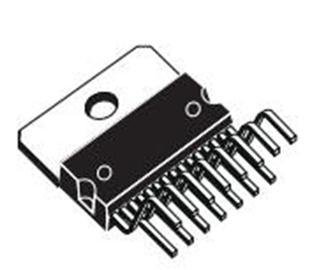
H-bridge circuits are used to control the direction of the rotation of the motor. The L298 is a dual H-Bridge circuit. It is composed of 2 H-Bridges, therefore a maximum of 2 motors can be controlled simultaneously. The amazing part of this component is that the control voltage reads logic level voltages, no need to compute for series resistors – you will have to simply connect the pin of the microcontroller (or any logic level devices) to the corresponding control pin of the L298 directly.
Given Example:
In this tutorial, we will use the L298 for driving and controlling a 1A DC Motor, with Vcc of 12V applied, and controlled by a PIC Microcontroller which I will be using for my steering wheels on my line follower robot.
Step 1: Begin with knowing the IC’s maximum ratings.
From the L298 datasheet shows the absolute max ratings.
The maximum voltage applied to the motor to be used (as well as the IC) is 50V. And the logic high input on the control voltage is 7V.
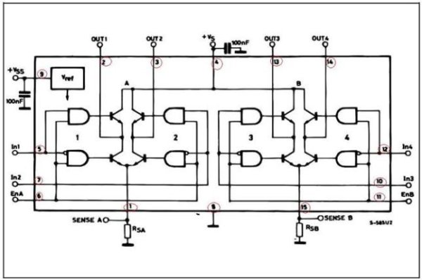
The Io or Output Current is one of the important factors that need to be considered. It is stated when you use a DC Motor, the maximum allowed current is 2 amps. If your motor requires a much larger current (for example 2.5Amps) then you might want to find other h-bridge devices.
In this case, the motor that we are using is rated 1A DC, Vs = 12V, and logic high supply from a microcontroller is 5V.
For more detail: IC-Based H-Bridge Tutorial
Quick Solutions to Questions related to L298 Motor Control:
-
What is the main advantage of using the L298 over a transistorized H-Bridge?
The L298 is very easy to control and does not require any calculation, as it accepts logic level voltages directly. -
How many motors can the L298 control simultaneously?
The L298 is composed of 2 H-Bridges, allowing it to control a maximum of 2 motors at the same time. -
Do I need to calculate series resistors when connecting the L298 to a microcontroller?
No, the control voltage reads logic level voltages, so you can connect the microcontroller pin directly to the L298 control pin. -
What is the maximum voltage allowed for the motor and the IC according to the datasheet?
The absolute max rating shows the maximum voltage applied to the motor and the IC is 50V. -
What is the maximum output current the L298 allows for a DC Motor?
The maximum allowed current is 2 amps; if a motor requires more, other h-bridge devices should be found. -
What is the logic high input voltage requirement for the L298?
The logic high input on the control voltage is 7V.
Related projects
Real-Time CAN-Based Vehicle Monitoring System with PIC MCU
INTRODUCTION The Controller Area Network (CAN) is a robust vehicle communication bus standard that was primarily developed for automobile applications but has...
Motors & RoboticsEasy Way to Learn Robotics Using Microcontrollers: A Beginner’s Guide
The title, "Easy Way to Learn Robotics Using Microcontrollers," promises an accessible entry point for those curious about the exciting world of...
Motors & Robotics · PIC16F877AEfficient Sun-Following Robot: A Solar Tracker with Microcontroller Control
Abstract The impending global challenge of dwindling non-renewable fuel resources underscores the urgency of transitioning towards renewable energy alternatives like solar power....
Motors & RoboticsInnovative Robotics: A Comprehensive Project Exploration
A DC motor functions as an electromechanical device, translating electrical signals into mechanical movements. The rotation of the motor correlates directly with...
Motors & RoboticsAdvanced Techniques for Fault Detection, Indication, and Protection in Induction Motors
1. INTRODUCTION The impact of microcontroller usage on our daily lives is remarkable. This versatile device is now prevalent in various control...
Motors & RoboticsExploring Versatility: GSM-Based Robotic Vehicle Technology
Introduction To Robotics The term 'Robot' remains elusive, defying a precise definition due to its evolving usage. Initially, it referred to humanoid...

Ibrar Ayyub
I am an experienced technical writer holding a Master's degree in computer science from BZU Multan, Pakistan University. With a background spanning various industries, particularly in home automation and engineering, I have honed my skills in crafting clear and concise content. Proficient in leveraging infographics and diagrams, I strive to simplify complex concepts for readers. My strength lies in thorough...