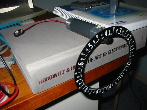
I can’t take credit for the design of this one. I bought the
gear as a clock a few years ago. It was mounted on a frame
and had one of those cheap clock units running it. The
gear is designed to be driven by the minute-hand shaft of
the clock mechanism.
The problem was that it kept breaking. I think the problem
was that the clock mechanism wasn’t strong enough to hold
the weight of the gear.
I bought a stepper motor with four input wires. A PIC
16F676 microcontroller functions as the timer. Every
three minutes, four output pins are driven either high
or low for half a second. These are each connected to
a pair of transistors – one PNP, one NPN to drive the
motor with more current. The stepper motor rotates 18
degrees each time.
For more detail: Gear Clock using PIC16F676 Microcontroller