
Summary of Electronic Distance Meter using pic microcontroller
This article describes a battery-operated bicycle distance meter using a Nitron 68HC908QY4 microcontroller and a 16x1 LCD. The device measures distance by detecting wheel rotations via a reed switch and a rare earth magnet, displaying results in meters.
Parts used in Bicycle Distance Meter:
- Nitron 68HC908QY4 16-pin MCU
- 16x1 line LCD module
- Rare earth magnet
- Reed switch sensor
- 0.1uF decoupling capacitor
- 16-pin SIP socket for LCD connector
- +5.1V zener diode
- Battery (9V or 1.5V x 3 AA)
- Small phone jack connectors
Measure distance while riding bicycle. Direct display in meter unit. Battery operated with Nitron 68HC908QY4, 16-pin MCU.
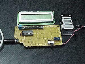
| Figure 1: Prototype of Distance Meter. |
This project demonstrates the use of 16×1 line LCD module to interface with Nitron 16-pin MCU, 68HC908QY4. The original idea came from one evening I went out with my son to the park near my home in Korat. The park has a nice walking way for people to exercise. I was wondering how long the distance is? I thought it would be nice if we know distance for one round.
 It seemed to me that it’s quite long, but I didn’t know exactly. My son ridden bicycle while I was walking along him. I look at the bicycle wheel, and thought may be we can measure distance with the help of wheel rolling. The week before I brought a magnet from BaanMor, it was the rare earth magnet.I thought why don’t have the reed switch as the sensor and use the magnet tied to a wheel. Detection of rolling is then made by proximity effect, when the magnet close to the reed switch. This close/open reed switch contact can use to make on-off signal. I chose MCU from Motorola, a 16-pin 68HC908QY4 for counting the pulse signal produced by reed switch.
Hardware Schematic
The MCU uses internal oscillator, internal reset, so we need only to supply the +VDD and VSS. I put the decoupling cap 0.1uF to VDD and VSS. Interface signals for LCD are D4-D7, RS and E. It was 4-bit interfacing, no BUSY checking. The LCD connector is 16-pin SIP socket. D0-D3 is not used, so we must tie to GND. Also R/W# was tied to GND. Since we can not check BUSY bit, so the delay routine must be used to wait LCD ready for command and data writing.
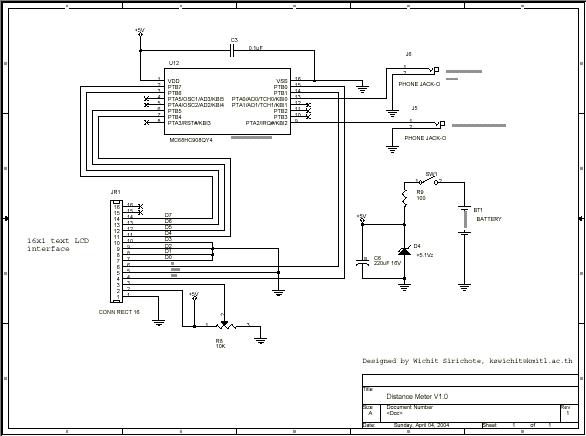 The sensor inputs are PTA2 for reed switch contact and PTA0 for 0/+5V analog input. I used small phone jack for both sensors. The analog input is optional. I haven’t got the idea what sensor should be used. The power supply is battery with simple +5.1V zener diode. You can use +9V battery or 1.5Vx3 AA battery. The circuit can run properly when the supply down to +3V. Care should be taken if you will use ADC, since the VREF is the same as VDD!
For more detail: Electronic Distance Meter
-
How does the device measure distance?
It uses a reed switch as a sensor and a rare earth magnet tied to the wheel; detection occurs when the magnet is close to the switch. -
Can I use a 9V battery for power?
Yes, you can use a +9V battery or three 1.5V AA batteries to power the circuit. -
What happens if the supply voltage drops to +3V?
The circuit can still run properly even when the supply drops to +3V. -
Does the LCD interface require BUSY checking?
No, the project uses 4-bit interfacing without BUSY checking, requiring delay routines instead. -
Which pins are unused on the LCD connector?
D0-D3 are not used and must be tied to GND, while R/W# is also tied to GND. -
What type of oscillator does the MCU use?
The MCU uses an internal oscillator and internal reset, needing only VDD and VSS connections. -
Why should care be taken if using ADC?
Care is needed because the VREF is the same as VDD when using the analog input feature.
