At home I have a salt lamp. This lamp needs a regular small 15 Watt light bulb that lights up and warms up the lamp. When the lamp is switched on you normally should not dim the lamp because of the lamp heat that the salt lamp needs to get rid of the moisture it attracts. Sometimes, however, I want to dim the lamp so it can be used as a night lamp.

I wanted to make life easier when switching every day from maximum brightness to a lower brightness so that’s why I created this Electronic Dimmer with Memory.
This dimmer uses one push button for controlling the following functions:
- Lamp off
- Lamp on
- Lamp dimmed
- Changing the brightness level
When the lamp is in dim mode, the brightness can be changed by pressing the bush button and holding is pressed. After a few seconds the brightness goes up until it is at its maximum. Releasing the push button and pressing it again while in dim mode, the brightness goes down until the lamp is off. The change in brightness stops as soon as the push button is released.
Both the mode (on, off or dimmed) and the brightness level in dim mode are remembered in case the dimmer itself is switched off and on again. When switching between modes, the last brightness value is used in dim mode. In this way it is easy to switch between the lamp being on or to a preset brightness level.
Step 1: Required Components
You need to have the following components for this project:
- A piece of breadboard
- PIC microcontroller 12F675
- Optocoupler MOC3020.
- 8 Volt center tapped transformer
- Fuse holder + fuse 1A/250V
- Electrolytic capacitor 470 uF/16V
- Voltage regulator 78L05
- Ceramic capacitors: 2 * 100nF, 2 * 22pF
- Resistors: 2 * 33k, 2 * 10k, 1 * 330 Ohm, 2 * 220 Ohm, 1 * 180 Ohm
- Diodes: 2 * 1N4148, 2 * 1N4004
- Transistor BC548
- Pushbutton
- Crystal 20 MHz
- LED: 1 Amber, 1 Green
Step 2: The Design of the Circuit & Timing

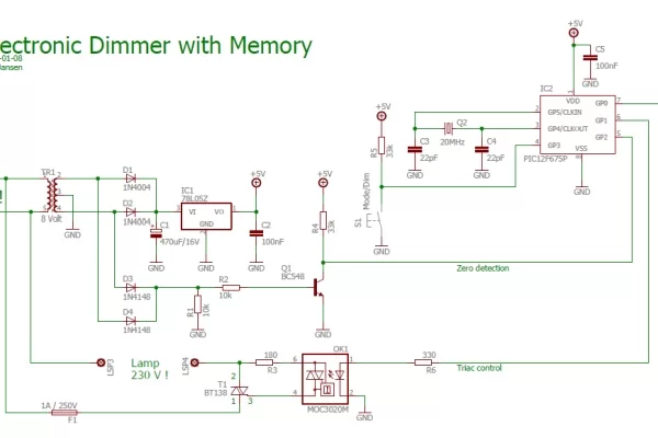
See the schematic diagram for the design of the circuit.
The use of a center tapped transformer, which I got from an old digital clock, made the design easy. With this type of transformer you can easily make a power supply using only two 1N4004 diodes instead of 4 diodes and create a zero detection circuit using the two 1N4148 diodes and the BC548 transistor.
The zero detection circuit is connected to the interrupt pin 5 of the PIC12F675 and generates an interrupt every 10 ms because of the 50 Hz mains power cyclel. Depending on the selected dim level, the PIC will trigger Triac BT138 sooner or later during the 50 Hz cycle using the optocoupler MOC3020. The later the Triac is triggered during the 50 Hz cycle, the lower the brightness of the lamp.
The first figure shows the trigger pulse of the Triac when the lamp is at its minimal brightness, in fact it is off because the Triac is triggered when the mains power is at the end of its 50 Hz cycle. The top signal is measured after the 1N4148 diodes so it is a rectified signal that is shown here.
The second figure shows the trigger pulse of the Triac when the lamp is at its maximum brightness. As you can see the trigger pulse is not completely at the start 50 Hz mains power cycle which is caused by the fact that the zero detection circuit does not generate an interrupt exactly at the start of the mains power but later. This means
there is a small increase in the brightness of the lamp from the maximum brightness to completely on but this is not visible.
The trigger signal for the Triac can be moved anywhere between the min and max values so controlling the brightness from completely on to completely off. This works well for larger, e.g. 40 Watt, lamps but also for smaller lamps like the 15 Watt lamp that I used. Not all dimmers you can buy are able to dim 15 W lamps but this one can.
The third figure shows the situation in which the lamp is dimmed to a low brightness by triggering the Triac near the end of the 50 Hz cycle.
In this design I used a crystal of 20 MHz for the processor clock since the on-board oscillator of the PIC is not accurate enough for this purpose.
Step 3: Building the Electronics

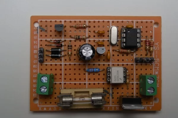
You can build the circuit on a breadboard but be very careful with the Fuse and the Triac that switch the mains power. Do not touch the mains power in any way!
In the pictures you can see the circuit as I build it on the breadboard. Normally I try to use as less as possible wires that cross other wires (the green and orange ones). The housing for this dimmer is a bit oversized but I could not find a smaller one.
I did not measure the power consumption of the circuit but I think that most power is consumed by the two LEDs and the optocoupler so I guess the whole circuit draws about 40 mA.
Step 4: The Software and the Operation of the Dimmer
As already mentioned, the software is written for a PIC12F675 but you can also make this for your Arduino. It was written in JAL and the program has quite some comments that explain what the various parts of the software are doing. Since I did not use any specific libraries the total code size is 533 bytes which fits nicely in the 1k program flash memory this specific controller has. This PIC has EEPROM on board which is used to store the last selected operating mode and the last selected brightness value.
The software performs the following main tasks:
- Read the EEPROM at power on and use the stored operating mode and brightness level. At first startup nothing is stored in EEPROM so it uses a default value. The default is set to lamp off and a brightness level of about 50% of the lamp brightness.
- Read the push button and change either the operating mode or the brightness level.
- Trigger the Triac synchronous with the 50 Hz mains power to switch the lamp on, off or dim. This trigger signal is generated on an interrupt basis using the zero detection signal as input.
- Store any change in operating mode or dim level in EEPROM.
Note that the software also has a test function. If you press the pushbutton while switching on the power of the dimmer, the dimmer will go into an endless loop, changing the brightness from minimum to maximum and back again. You have to switch the dimmer off and on again – and not press the pushbutton – to get the dimmer out of this mode.
The video shows how it all works in practice. In this video you see the following:
- The dimmer is switched on. The green power LED is on and the lamp is off.
- Pressing the push button once turns the lamp on.
- Pressing the push button again switches the dimmer to dim mode. The amber dim LED is on indicating that the dim mode is active and a default brightness level is used.
- Pressing the push button again switches the lamp off.
- Pressing the push button once turns the lamp on.
- Pressing the push button again switched the lamp to dim mode.
- Pressing and keeping the push button pressed while in dim mode increases the brightness of the lamp.
- Releasing, pressing and keeping the push button pressed while in dim mode decreases the brightness of the lamp.
- Switching the dimmer off and on again (green LED goes off and on) sets the dimmer to the last operating mode. In this case it was the dim mode with the last brightness value (amber LED is on).
- Pressing the push button switched the lamp off.
The Intel Hex file and the JAL source file are attached. I renamed the JAL file from ‘.JAL’ to ‘.TXT’ for readability.
Have fun building your own project and looking forward to your reactions.
Attachments
Source: Electronic Dimmer With Memory
