Summary of ELECTRONIC ANTI FOULING CIRCUIT BOATS FOR SAVERS ULTRASONIC PIC12F675
This article describes an electronic anti-fouling circuit designed for boat motors to prevent damage from crustaceans and parasites using ultrasonic signals. The system utilizes a PIC12F675 microcontroller programmed in assembly language to drive a Piezzo sonic transducer via an ETD29 transformer. Operating on 12V DC, the circuit generates high-voltage AC output (up to 800V) to emit ultrasonic frequencies, which can also be adapted for pest control in homes and gardens.
Parts used in the Electronic Anti Fouling Boat Motor:
- PIC12F675 microcontroller
- TL499 integrated circuit
- Piezzo sonic transducer speaker
- ETD29 transformer
- 12 volts DC power supply
- Printed circuit board (PCB)
- Oscilloscope
Electronic Antifouling Boat motor propeller parts of the body causing damage to the wood adhesive crustaceans, protozoa, parasites, and so on. who do harmful things such as ultrasonic signals out with a circuit… Electronics Projects, Electronic Anti fouling Circuit Boats for Savers Ultrasonic PIC12F675″microchip projects, microcontroller projects, “
Electronic Anti fouling Boat motor propeller parts of the body causing damage to the wood adhesive crustaceans, protozoa, parasites, and so on. who do harmful things such as ultrasonic signals out with a circuit ultrasonic mouse repellent circuit as you know 🙂 This circuit is designed for boats and power boats adjusted frequency range.
As will be useful to a lot of boat owners with pic ultrasonic signal generation and so on. pic programming dealing with issues such as resource person in a nice
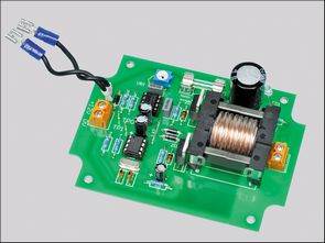
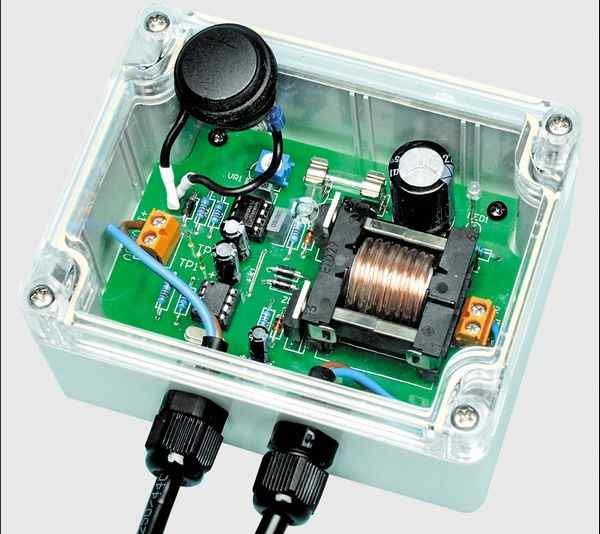
Ultrasonic Anti-fouling of circuit tl499, used 12 volts DC is working with pic12f675 integrated ultra-sonic transducer (Piezzo sonic speaker) can be used to drive ETD29 transformer ETD29 transformer windings used instead probably picture has been described in details.
ELECTRONIC ANTI FOULING CIRCUIT ULTRASONIC
Software written in assembly language PIC12F675 source. Asm,. Hex codes printed circuit board pcb circuit diagram box has dimensions oscilloscope measurement chart.
Piezzo sonic transducer speaker version … 800V AC 250v circuit voltage is too high in tests, hot-touch-hander transformer output is
Finally, perhaps by changing the frequency of the circuit in homes, gardens of the pests, pests can be used in the ultrasonic fouling circuit 🙂
Source: ELECTRONIC ANTI FOULING CIRCUIT BOATS FOR SAVERS ULTRASONIC PIC12F675 Anti fouling project alternative link:electronic-anti-fouling-boats-for-savers-ultrasonic-pic12f675.rar
- What is the primary purpose of this circuit?
The circuit is designed to prevent damage to boat motor propellers and bodies caused by wood adhesive crustaceans, protozoa, and parasites. - Which microcontroller is used in the project?
The project uses the PIC12F675 microcontroller. - How does the circuit generate ultrasonic signals?
It uses a circuit that outputs ultrasonic signals driven by a Piezzo sonic transducer connected to an ETD29 transformer. - What voltage does the system operate on?
The circuit works with a 12 volts DC power supply. - Can the frequency be adjusted for other uses?
Yes, changing the frequency allows the circuit to be used for pest control in homes and gardens. - What programming language was used for the software?
The software was written in assembly language. - What is the maximum AC voltage output tested?
Tests showed the circuit could produce up to 800V AC at the transformer output. - Is there a specific transformer required for the design?
The design specifies using an ETD29 transformer with its windings described in detail.