Summary of DIY Datalocker
Summary: This project converts a standard external SATA hard-drive enclosure into a PIN-protected datalocker using a PIC16F628A microcontroller, a 3x4 keypad, a relay to switch drive power, and supporting components. You remove the enclosure board, wire power and USB pins for the PIC supply, assemble the control circuit, program the PIC with the provided HEX file, mount components, and cut the protoboard to fit before final assembly.
Parts used in the Datalocker:
- 3.5" SATA harddrive enclosure
- 2.5" SATA harddrive
- LED with resistor (for 5V)
- 3x4 matrix keypad
- 470 Ohm resistors (4x)
- PIC 16F628A microcontroller
- 5 or 6 Volt relay, 1 Amp
- 1N4148 diode
- BC337 transistor (or similar)
- 2K2 resistor
- Prototyping board
- Soldering wire/wires for connections
- Hot glue (for mounting)
- Double sided tape
Step 1: Parts
The parts you need:
– 3.5″ SATA harddrive enclosure
– 2.5″ SATA harddrive
NOTE: This will not work with a 3.5″ IDE enclosure and a 2.5″ IDE drive without a special adapter, they have different connectors.
– LED with resistor to power it from 5 Volts
– 3×4 Matrix keypad
– 470 Ohm resistors (4x)
– PIC 16F628A microcontroller
– 5 or 6 Volt relay, 1 Amp should be enough
– 1N4148 diode (Without this you will fry your USB port)
– BC337 transistor (or similar)
– 2K2 resistor
– Some prototyping board
Tools:
– Hot glue gun
– Soldering iron and solder
– Double sided tape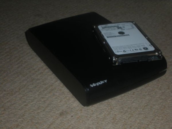
Step 2: Preparing the USB board.
First you need to disassemble the hard drive enclosure and take out the board.
Then you have to desolder the power connector and solder wires where the connector was.
After you have done that, solder the pin on the back of the power connector to the corresponding wire.
(The one that is now where the pin on the back of the connector used to be)
Last, solder wires to the other two pins of the power connector.
Step 3: Finding a power source for the PIC
Now you need to find a way to power the PIC.
I think the easiest way is to solder wires to the usb connector. If the connector on your board is a SMD type and/or the pins are hard to reach, find a solder connection that is connected to the correct pin of the USB connector.
I chose to solder a wire to a via (a little hole in the board that carries a trace from one side to the other) for the positive connection and another one to the metal shielding of the USB connector for the negative connection.
The second picture shows the connections on the different types of USB connectors.
1: Positive
2: Data –
3: Data +
4: Ground (negative)
Step 4: Build the circuit
Build the circuit that will be controlling the drive according to the schematic.
The design, as well as the code for the PIC are based on this
The circuit is built around the PIC 16F628A microcontroller, which needs to be programmed with the attached HEX file.
Build the circuit but do not connect everything yet! (see the notes on the schematic)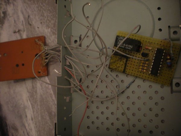
Step 5: Cutting the circuit board to the right size
Before we connect all the wires, we need to cut the circuit board to size, it would be difficult do do this afterwards.
Start by planning where you are going to connect all the wires, mark where you are going to cut the circuit board and then cut it.
For more detail: DIY Datalocker
- Can I use a 3.5 IDE enclosure with a 2.5 IDE drive?
No. The article notes this will not work without a special adapter because they have different connectors. - What microcontroller is used to control the datalocker?
The PIC 16F628A microcontroller is used. - How is the PIC powered in this project?
The PIC is powered by soldering wires to the USB connector or to a solder connection/via tied to the USB power pin. - Do I need to program the PIC and how?
Yes. The PIC must be programmed with the provided HEX file as stated in the article. - What protects the USB port from damage when switching drive power?
The 1N4148 diode is included to prevent frying the USB port as noted in the parts list. - How is the drive power switched on and off?
A 5 or 6 Volt relay rated about 1 Amp is used to control the drive power. - What tools are required for assembly?
A hot glue gun, soldering iron and solder, and double sided tape are listed as tools. - When should I cut the prototyping board to size?
Cut the prototyping board before connecting all wires and before final assembly to make fitting easier. - Where do I solder wires after removing the enclosure board?
Solder wires where the power connector was and to the corresponding pin on the back of the connector, plus to the other two power connector pins as described.