Summary of Digitally Controlled Bench PSU
This article discusses a hobbyist's project to design an affordable, digitally controlled bench power supply (0–30V, 0–3A) using modern, cost-effective components. Unlike expensive commercial units with potentiometers, this design uses a keyboard interface for precise voltage and current adjustments in small steps. The author shares preliminary schematics and notes that while the base design targets 90W output, it can be scaled to higher voltages and currents with component recalibration.
Parts used in Digitally Controlled Bench PSU:
- Keyboard interface
- Digital control circuitry
- Preliminary schematic components
- Voltage regulation components
- Current regulation components
Many electronics people will build a bench power supply at one point in their professional or hobby career. I too have made a couple over the years. However, most of the time I used what was available in the shop(s) where I did my work. One type of PSU in particular always fascinated me: a digitally controlled PSU. No potentiometers, but a keyboard where you punch in the numbers and get exactly that.
Those digitally controlled PSUs are rather expensive toys. Of course depending on the actual accuracy, but they are not the cheapo China stuff you often see. So I started wondering what it would take to design one on a reasonable budget. 25 years ago, when I saw the first digital PSU, it would have been all too expensive for a hobbyist to come by. Most of the electronics are now affordable and it should be possible to, at least, “take a cursory design look”.
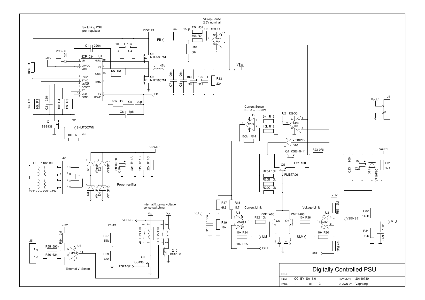
Attached is a schematic that should show my thoughts so far.
 psudig_sch.pdf
- Preliminary schematics
- (40.91 KiB) Downloaded 858 times
The design is for 0…30V and 0…3A (90W) controllable at ~1mV and ~0.1mA steps. The actual accuracy is still out for testing and I assume that noise and non-linearity will be a factor to look at when time comes. The basic design allows for 0…42V (max 45V) and (at least) 0…4A, but then all the components should be re-calculated to match such setup. Also, some components need to be voltage matched for a higher input voltage.
For more detail: Digitally Controlled Bench PSU
- Why did the author decide to build this project?
To create a digitally controlled power supply on a reasonable budget since commercial models are expensive. - What is the target output range of the initial design?
The design targets 0 to 30 volts and 0 to 3 amps. - How does the user adjust the settings on this unit?
Users punch in numbers via a keyboard rather than using potentiometers. - What are the control step sizes for voltage and current?
The system allows control at approximately 1mV and 0.1mA steps. - Can this design be modified for higher power output?
Yes, the basic design allows for up to 45V and 4A if components are re-calculated. - Are accuracy factors like noise currently confirmed?
No, actual accuracy and noise levels are still pending testing. - What is the maximum voltage capability mentioned for the basic design?
The basic design allows for a maximum of 45 volts.