Summary of DIGITAL VOLTAGE PROBE PIC18F242
Summary: This article describes building a digital voltage probe using a PIC18F242 microcontroller. It measures voltage with the PIC's ADC and displays values on an LCD both digitally and as an analog-style bar; LEDs indicate logic states. The design uses a crystal oscillator, includes Proteus ISIS simulation, and provides C source code.
Parts used in the Voltage Probe:
- PIC18F242 microcontroller
- LCD display
- LED indicators
- Crystal oscillator (crystal, OSC and OSCOUT connections)
- Analog input voltage source (probe connection)
- Resistors (for LEDs and input scaling)
- Capacitors (for oscillator and decoupling)
- Proteus ISIS simulation files
- C source code files
Hello In this article we will talk about Making Voltage Probe. First, let me explain what is the voltage probe. Voltage Probe, displays the amount of voltage at one point. In addition to a… Electronics Projects, Digital Voltage Probe PIC18F242 “microchip projects, microcontroller projects, “
Hello
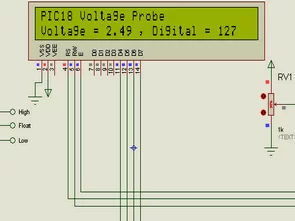
In this article we will talk about Making Voltage Probe. First, let me explain what is the voltage probe. Voltage Probe, displays the amount of voltage at one point. In addition to a digital value, may include features such as logic states.
We will do a digital voltage probes made with the PIC18F242 Voltage Probe. To measure the voltage of the built-in PIC 10-Bit 10-Bit adc’s the kullanacağız.ancak not as I’ve used the 8-Bit.
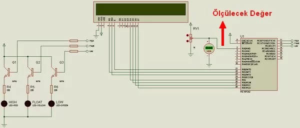
Value of the voltage on the LCD digital and analog displays. LEDs show the value of the corresponding logic.
Because I use crystal oscillator circuit simulation. Circuit the oscillator OSC and OSCOUT a general connection between the terminals can be established.
ISIS simulation and source code are attached.
Source: DIGITAL VOLTAGE PROBE PIC18F242 App of the isis proteus simulation and C code files: digital-voltage-probe-pic18f242.ZIP
- What does the voltage probe display?
The voltage probe displays the amount of voltage at one point as a digital value and also provides an analog-style display; LEDs show corresponding logic states. - Which microcontroller is used in this project?
The project uses the PIC18F242 microcontroller. - How is the voltage measured?
Voltage is measured using the PIC18F242 built-in ADC (10-bit ADC referenced in the article). - How are the results shown to the user?
Results are shown on an LCD as digital and analog displays, and LEDs indicate logic states. - Does the project include simulation files?
Yes, Proteus ISIS simulation files are included with the project. - Is source code provided for the project?
Yes, C source code files are provided with the project. - Does the design use a crystal oscillator?
Yes, the design uses a crystal oscillator with OSC and OSCOUT terminal connections. - Can LEDs indicate logic states in this probe?
Yes, LEDs are used to show the value of the corresponding logic states.