The traditional three op-amp differential amplifier’s signal to noise ratio can be improved by 6dB by adding a resistor and slightly changing the connections. There is a trade-off though: The traditional topology has a high input impedance, whereas the low-noise version has a lower input impedance.
Figure 1 depicts a traditional three op-amp differential amplifier. For the sake of simplicity we will assume that A3 is an ideal noiseless opamp and the four resistors labeled R6 are exactlyequal, so that the output of A3 is given exactly by V1 – V2. The A3 circuit is a perfect subtractor. We will also assume that the two resistors labeled R1 are exactly equal. The outputs are given by:
V1 = + (Vs/2)( 1 + 2r ) + Vn1 ( 1 + r ) + Vn2 ( r )
V2 = – (Vs/2)( 1 + 2r ) – Vn2 ( 1 + r ) – Vn1 ( r )
Vout = Vs ( 1 + 2r ) + Vn1 ( 1 +2r ) + Vn2 ( 1 + 2r )
Where:
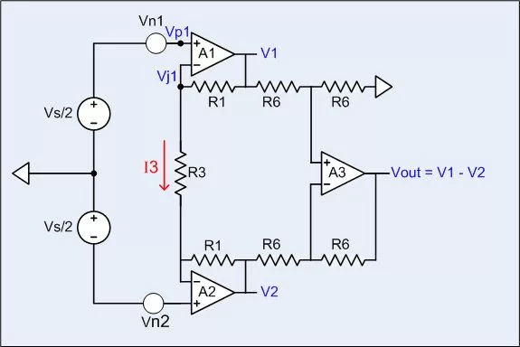
r = R1/R3
Vn1 = voltage noise from opamp A1, RMS value = Vn
Vn2 = voltage noise from opamp A2, RMS value = Vn
If R1 = 20kΩ and R3 = 1kΩ, then:
Vout = 41Vs + 41Vn1 + 41Vn2
Vn1 and Vn2 are random, so that the polarity can be chosen for convenience. The signal and the noise sources all have the same gain, so the signal to noise power ratio is Vs² / ( 2 Vn² ).
Figure 2 depicts the circuit of this Design Idea. Resistor R3 has been duplicated and its hookup modified. The outputs of this circuit are given by:
V1 = + (Vs/2)( 1 + 2r ) + Vn1 ( 1 + r )
V2 = – (Vs/2)( 1 + 2r ) – Vn2 ( 1 + r )
Vout = Vs ( 1 + 2r ) + Vn1 ( 1 + r ) + Vn2 ( 1 + r )
Where r = R1/R3
If R1 = 20kΩ, and R3a = R3b = R3 = 1kΩ then:
Vout = 41Vs + 21Vn1 + 21Vn2
The output signal to noise power ratio is ( 41 Vs )² / ( ( 21 Vn )² + ( 21 Vn)² ), which is almost equal to 2 Vs² / Vn². That is about 6dB better than the traditional circuit. What is going on?
The answer is revealed by looking at the outputs of A1 and A2 in the traditional circuit. The output of A1 has a noise component due to its own noise, and an almost equal component due to the noise from A2, which also has noise components from both op-amps. In the new circuit, the output of each opamp has noise only from its own internal noise source.
The connection between A1 and A2 is through R3. A1’s internal voltage noise source, Vn1, drives its internal non-inverting input, Vp1, which causes the output of A1 tohave a noise component from its own noise source. Normal negative feedback action causes A1’s summing junction to follow its non-inverting input, meaning A1’s internal noise will appear on its summing junction, Vj1, which will drive a noise current into R3 that will be injected into the summing junction of A2. In this way, the noise source in A1 appears at the output of both A1 and A2. Likewise the noise source in A2 appears in the output of both A1 and A2.
For more detail: Differential amp has 6dB lower noise, twice the bandwidth