Summary of CAR SPEED ALARM CIRCUIT DISPLAY INDICATOR PIC16F84A
This article describes a car speed alarm circuit using the PIC16F84A microcontroller. The project features a front panel with a 3-digit LED display, an indicator LED, and three pushbutton switches. Users can set an alarm speed between 0 and 155 km/h in 5 km increments. When the vehicle exceeds this limit, the LED lights up, and an internal piezo alarm sounds every 10 seconds. Source code, schematics, and PCB files are available for download.
Parts used in the Car Speed Alarm Circuit:
- PIC16F84A microcontroller
- 3-digit LED display
- LED indicator
- Three pushbutton switches
- Internal piezo alarm
speed alarm circuit PIC16F84A microcontroller used in the project’s source code, schematics and PCB files are there. It’s also just as easy to drive as before. As shown, the front panel carries a 3-digit LED display, a LED indicator… Electronics Projects, Car Speed Alarm Circuit Display Indicator PIC16F84A “microchip projects, microcontroller projects, pic assembly example, pic16f84 projects,
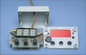
speed alarm circuit PIC16F84A microcontroller used in the project’s source code, schematics and PCB files are there.
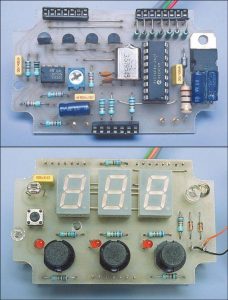
It’s also just as easy to drive as before. As shown, the front panel carries a 3-digit LED display, a LED indicator and three pushbutton switches. Two of these pushbuttons let you set the alarm speed in 5km increments between 0km/h and 155km/h (one switch increases the speed; the other reduces it). As soon as you exceed the preset speed, the indicator LED lights and an internal piezo alarm briefly sounds at 10-second intervals to provide a warning
PIC16F84A CAR SPEED ALARM
Source: http://www.siliconchip.com.au/cms/A_103208/article.html
Car Speed Alarm Circuit PCB schematic Display Indicator PIC16F84A pic assembly source code Alternative link:
FILE DOWNLOAD LINK LIST (in TXT format): LINKS-2629.zip
Source: CAR SPEED ALARM CIRCUIT DISPLAY INDICATOR PIC16F84A
- How do you set the alarm speed?
Use two of the pushbuttons to increase or decrease the speed in 5km increments between 0km/h and 155km/h. - What happens when the preset speed is exceeded?
The indicator LED lights up and an internal piezo alarm briefly sounds at 10-second intervals. - Does the circuit use a microcontroller?
Yes, it uses a PIC16F84A microcontroller. - What components are on the front panel?
The front panel carries a 3-digit LED display, an LED indicator, and three pushbutton switches. - Can I access the source code for this project?
Yes, the source code, schematics, and PCB files are available for download. - What is the maximum speed setting for the alarm?
The maximum preset speed is 155km/h. - How often does the alarm sound if triggered?
The internal piezo alarm sounds briefly at 10-second intervals. - Are there links to download the project files?
Yes, a file download link list in TXT format is provided.