
Summary of Car Anti theft System Project using Microcontroller PIC16f73
This article details a vehicle anti-theft system using a PIC16F73 microcontroller. The project locks the wheel if it rotates beyond a preset limit while the key is off. It utilizes an IR sensor pair to detect wheel movement via a slotted disk, counting pulses with TIMER0. The system includes indicators for status and locking, plus a buzzer alarm, all controlled by the microprocessor's logic.
Parts used in the Vehicle Anti Theft System:
- PIC 16F73
- Transistor BC 548 X 2
- Zener diode
- Photodiode
- IR Led
- Capacitors (33pFx2;10uF)
- Resistors (1k x5; 330 ohmX2)
- Buzzer
- Relay
- HITECH C compiler
- Crystal frequency 20 Mhz
For a while we have been sharing many electronic projects for engineering students and then we found out there was a huge demand for embedded projects, especially PIC microcontroller based projects. After a short break, here is another outstanding one that is not only suitable for electronics engineering but mechanical engineering students too.
Now coming to the project topic, as seen from the title it’s related to security systems which is of main concern these days.
This vehicle anti theft system will lock the wheel when it rotates more than preset cycles whenever the key is in OFF condition. The main component of the circuit is PIC16F73; it’s compatible for PIC16F877A also but I have used PIC16F73 as it’s comparatively small (28 pin). It uses an IR sensor system to detect rotation of the wheel.
Circuit diagram of anti theft system for cars
Components Required
- PIC 16F73
- Transistor BC 548 X 2
- Zener diode
- Photodiode
- IR Led
- Capacitors (33pFx2;10uF)
- Resistors (1k x5; 330 ohmX2)
- Buzzer
Working
- An IR LED and photo diode pair is used to detect rotation of the wheel. It’s attached with a disk which has openings; IR rays will pass through these openings.
- When the wheel is rotating, IR rays will be cut by the disk openings which will make a pulse output on the photo diode.
- Output of photo diode is connected to external clock input pin of TIMER0/COUNTER0 of the PIC.
- Pulses from the photo diode are counted by the counter. Each time the counter value is compared against the pre-set value and it will set the RC1 (1st pin PORTC).

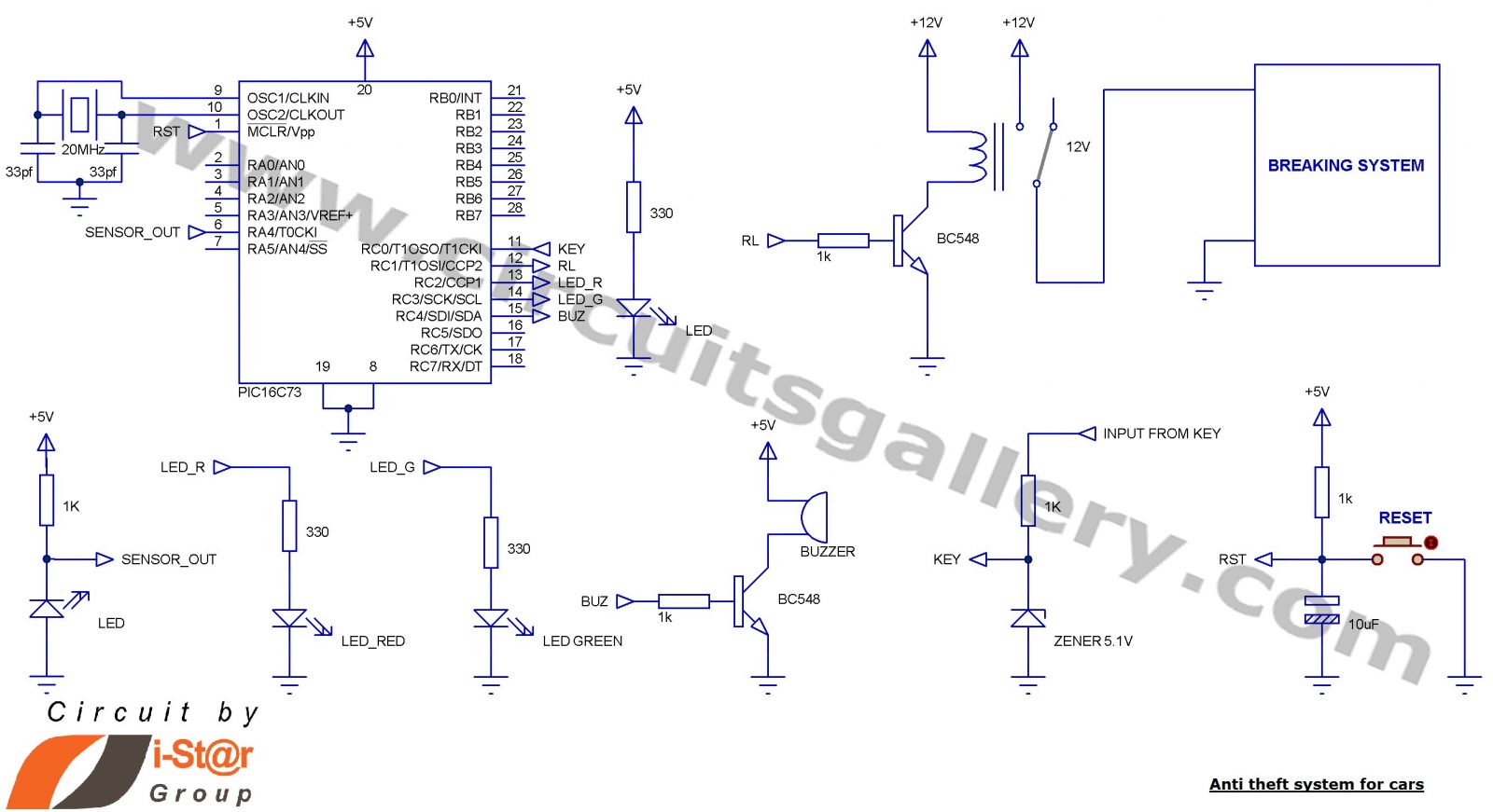
- The relay used to control the locking device is connected at RC1. RC0 is used to check the key condition, locking is done only when the key is under OFF condition.
- The input from key can be +12V, it is regulated by a 5.1V zener diode connected in the circuit as PIC can’t connect +12V.
- RC2 is used to indicate that the system is working; here we connect a green LED which will start blinking when the system is ready.
- RC3 is used to connect an LED to indicate that the locking device is ON or OFF; it will set when locking occurs.
- RC4 is used to connect a buzzer to indicate that the preset rotation cycle has reached and system is going to lock the wheel, it will be ON for 1 second and after that it will reset.
- I have used HITECH C compiler to compile the program. Crystal frequency used is 20 Mhz.
For more detail: Car Anti theft System Project using Microcontroller PIC16f73
- How does the system detect wheel rotation?
An IR LED and photodiode pair detects rotation as rays pass through openings on a disk attached to the wheel. - Can the PIC16F877A be used instead of the PIC16F73?
Yes, the PIC16F877A is compatible, though the author chose the smaller 28-pin PIC16F73. - What condition must be met for the locking mechanism to activate?
Locking occurs only when the key is in the OFF condition and the wheel rotates more than the preset cycles. - How is the +12V key input handled in the circuit?
The +12V input is regulated by a 5.1V zener diode because the PIC cannot connect directly to +12V. - Which pin indicates that the system is working?
RC2 is used to connect a green LED that starts blinking when the system is ready. - What happens when the preset rotation cycle is reached?
A buzzer connected to RC4 turns ON for one second before resetting as the system prepares to lock the wheel. - What compiler was used for the program?
The HITECH C compiler was used to compile the program. - What crystal frequency is used in this project?
A crystal frequency of 20 Mhz is used.
