Summary of Bluetooth-Controlled Guitar FX Amplifier
This project is a Bluetooth-controlled guitar amplifier featuring remote digital effects and physical tone knobs. It integrates analog circuitry for distortion and tone shaping with a PIC32 microcontroller managing a Belton BTSE-16 digital effects chip via UART. The system allows users to adjust bass, treble, and mid frequencies physically or digitally through a smartphone interface, adhering to IEEE 802.15.1 Bluetooth standards for wireless communication in the 2.4 GHz band.
Parts used in the Bluetooth-Controlled Guitar FX Amplifier:
- Belton BTSE-16FX digital audio effects chip
- PIC32 microcontroller
- HC-05 Bluetooth module
- TPA3122D2 15 Watt Class-D power amplifier
- LF353 operational amplifiers
- 10k and 100k resistors
- 100 nF and 10 uF capacitors
- Schottky diodes
- 1/4 inch TS Male Auxiliary cord
- 1/4 inch TS female to 3.5 mm TRS male adaptor
- Physical potentiometers for bass, treble, mid, and level
- Inductor and capacitor for low-pass filter
As part of our final project for ECE 4760: Digital Systems Design Using Microcontrollers, we built a guitar amplifier with remote distortion and digital effects capabilities controlled from a smartphone via bluetooth.
Musicians often need to modify the configuration of their amplifiers when performing in concerts. This job is generally delegated to “roadies” who walk on-stage between sets to make adjustments. By building on top of generic amplifier circuitry we’ve been able to increase the capabilities of the standard guitar amp to allow remote control over all aspects of the amplifier’s sound.
High-Level Design
Things I Can Do
There are two methods of interfacing with the amplifier. The first resembles a classic guitar amplifier where the user controls the analog effects via knobs connected to analog potentiometers. As is standard, the input of the amplifier comes from a ¼” TS Male Auxiliary cord attached to an electric or acoustic guitar. We have a ¼” TS female to 3.5 mm TRS male adaptor. This in turn connects to a 3.5 mm adaptor which is wired directly into our circuit.
The second style of interfacing with the amplifier is via the PIC32 microcontroller which controls and applies digital effects. These sound effects are outputs of a Belton BTSE-16 chip, which, through onboard DSP, synthesize various effects. These effects include chorus, flanger, phaser, tremolo, delay, reverb, and various combinations thereof.
As part of our ‘stretch goal’, the primary standard to which we’ve conformed is determined by the Bluetooth Special Interest Group (SIG). The standard for Bluetooth that we will be following is set by IEEE 802.15.1. The standard essentially sets the MAC addresses available for our use as well as limits our applications to the 2.4-2.485 GHz ISM band.
Analog Circuitry
A large portion of the project was devoted to building and testing standard analog circuitry for generating our desired effects. The schematics for these are included below.
Distortion
Our input goes through a common emitter amplifier with the 10k and 100k resistors deciding the gain of the circuit. The 100 nF and 10 uF capacitors decide the frequency response of the circuit with a lower input capacitance creating a more treble-heavy sound and a higher input capacitance creating a more bass-heavy sound. The schottky diodes act as clipping diodes creating the distorted sound we hear at the output.
Tone Stack
Our input goes through a high pass filter into a unity gain op amp (pins 1,2, and 3). The treble potentiometer adjusts a high-pass filter that sets the cutoff frequency below which no frequencies can pass. The bass potentiometer adjusts a low-pass filter that sets the cutoff frequency above which no frequencies can pass. The mid potentiometer acts as a band-pass filter that amplifies the center frequency about which treble and bass act. The level potentiometer changes the magnitude of the output signal by altering the gain of the second op-amp (pins 5, 6, and 7). Pins 4 and 8 are the ground and Vdd (8.84 Volts) of the op-amp respectively.This schematic was found on Run Off Groove. We modified the circuit to use LF353 op amps, as they gave the desired performance and were readily available.
Class-D Amplifier
We used a TPA3122D2 15 Watt Class-D power amplifier in order to drive the signal to our speakers. The class-D amplifier uses pulse width modulation to take our analog input signal, convert it into pulses, and amplify the signal. In order to set the voltage high enough to drive the speaker, a capacitor is placed between the FET-driven output and the bootstrap pin. The amplified pulse train is converted back into an analog signal with the passive low-pass filter (capacitor and inductor) out of the ROUT pins of the chip (pins 12 and 13). This low-pass filter acts as an integrator to the PWM. Finally, we add DC offset to our signal with our 470 uF capacitor in order to output a audible signal to our speakers, without negative output.
Digital Circuitry and Microcontroller Integration
An even greater portion of the project was dedicated to digital design and microcontroller programming…
Digital Effects Chip
The BTSE-16FX effect board provides 16 different digital audio effects when integrated into the amp. On the highest level, the chip takes in an input signal (sound wave), a 4-bit binary select signal, and outputs an affected signal. The schematic shown to the left demonstrates one way to set up the chip which involves stepping down a voltage to power the chip, filtering an input signal, and filtering the output signal. We modified this schematic by replacing the input voltage circuit with a simple 5-volt power supply, replacing the input filtering with a simple high-pass filter, and removing the output circuit entirely by operating directly on the output of the chip.
The 4-bit binary select signal for choosing an effect was generated directly off the Pic32. A user would make a choice for effect via his or her smartphone, and the resulting bluetooth signal is read via uart and translated to a 4-bit logic output.
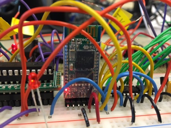
HC-05 Bluetooth Module
The HC-05 bluetooth module handles almost all responsibilities associated with establishing a bluetooth connection with any other bluetooth-enabled device. The HC-05 communicates over UART with the PIC which both transmits and received data. The chip works by publishing a bluetooth service and allowing another client – the smartphone – to pair with the module. Through the use of a bluetooth terminal on a smartphone (eg. blu-term) one can send data and test the uart connection with the PIC.
Read More: Bluetooth-Controlled Guitar FX Amplifier
- How does the user control the amplifier digitally?
The user makes effect choices via a smartphone, sending data through the HC-05 Bluetooth module which communicates over UART to the PIC32 microcontroller. - What digital effects can the Belton BTSE-16 chip produce?
The chip synthesizes chorus, flanger, phaser, tremolo, delay, reverb, and various combinations thereof. - Which standard does the Bluetooth implementation follow?
The project conforms to the Bluetooth Special Interest Group standard set by IEEE 802.15.1. - How is the distorted sound generated in the analog circuit?
Schottky diodes act as clipping diodes within a common emitter amplifier to create the distorted sound. - What role do the 100 nF and 10 uF capacitors play?
These capacitors decide the frequency response, where lower input capacitance creates a treble-heavy sound and higher capacitance creates a bass-heavy sound. - How does the Class-D amplifier convert the signal for speakers?
It uses pulse width modulation to convert the analog input into pulses, then converts the amplified pulse train back to an analog signal using a passive low-pass filter. - What is the function of the 470 uF capacitor in the output stage?
This capacitor adds DC offset to the signal to ensure an audible output without negative voltage. - How are the physical knobs utilized for tone adjustment?
The treble knob adjusts a high-pass filter, the bass knob adjusts a low-pass filter, and the mid knob acts as a band-pass filter.