


Summary of Automated Power Tool Charger
This article describes a DIY project to automate daily charging for power tool batteries using a PIC12F675 microcontroller. The device ensures batteries remain charged with a 30-minute daily cycle but offers an 8-hour manual override for recharging depleted batteries after use. It utilizes line frequency for accurate timing and includes visual indicators for power and charging states.Parts used in the Automated Power Tool Charger:
- PIC12F675 Microchip Controller
- 220/14V Transformer
- Rectifier Diodes (D1..D4)
- Filter Capacitors (C1..C5)
- 7805 Voltage Regulator (+5V)
- 7812 Voltage Regulator (+12V)
- Relay (K1)
- Driver Transistor (Q1) and Resistors (R1, R2, R5)
- Override Switch (S2)
- Power Indication LED (D6) and Charge Indication LED (D7)
- Resistors (R3, R4, R6, R7)
- Jumper J2 for 50Hz/60Hz selection
- Plastic light switch box
- On/Off Light Switch
- Bell of Dimmer Push Button Switch
Electric power tools changed the way most of us work around the house. Simple and quick, as no extension cords are needed. But they do come with some effort. I still have some power tools that are powered by old Ni-Cad or Ni-Mh batteries. They work great, but if they are not used on a weekly basis, the chances are good that their batteries will be drained when you want to use then. Thus, they need to be charged first before use. And some of the charges can take up to 14 hours to fully charge the batteries.
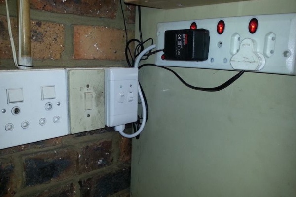
When the tools are not in use, a daily charge of around 30 minutes will keep the batteries fully charged, and the tool ready for use. So a normal programmable daily timer will work great in keeping the batteries full.
However, after using the power tools, their batteries will not be fully charged anymore. And a daily timer of 30 minutes will take several days, if at all, to recharge the batteries. Most programmable daily timer do have a manual override function that can be turned on to first charge the batteries. Then, after the batteries are charged, one needs to switch off the override function to continue the daily charge.
The idea of this project was to switch on the battery chargers on a daily basis. But after using the power tools, I also wanted to have the option to extend the charging time to recharge the batteries first.
Step 1: The Concept
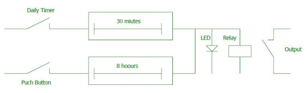
- To create a device that will automatically turn on for a set duration on a daily basis.
- To have an override function that will turn on the device for an extended period, then automatically reset the override.
Step 2: Using a Microchip PIC12F675
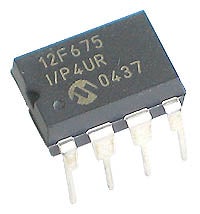
I decided to make use of a PIC 12F675 controller. They are cheap, and I had some spare. But keeping time with the 12F675 over a long period of time, will require some external components.
Their are three ways to keep time on a micro controller:
- Via software routines and delays - Good for short delays, or non-time critical applications. Will not work for this project.
- External Real Time Clock - Obvious the best option, regarding accuracy. But too expensive and more components.
- Power Line Frequency - Sounded like a good, cheap and relatively accurate option.
Step 3: How the Circuit Works
Power Supply
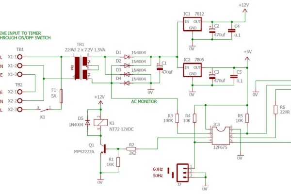
Power for the electronics is via a 220/14V transformer, which is rectified and filtered (D1 .. D4, C1). There are two regulators, a 7805 for the +5V for electronics (IC2, C3, C5), and a 7812 for the +12V (IC1, C2, C4) needed for the relay. I did not have 5V relays at hand, so this can be changed.
Relay and Driver
The relay is switched on/of by pin 3 of the chip. This in turn is used to switch the power on/off to the chargers (R1, R2, Q1, D5, K1).
Timer Override Switch
The override switch (S2) is connected to pin 7 of the chip. R5 is a pull-up resistor to keep the input pin at +5V when the button is not pressed.
Indication LEDs
The is a power indication LED (D6 and R6) and a charge indication LED (D7 and R7) to indicate the state of the timer.
Timing
To get relative accurate timing over a long period, I decided to make use of the line frequency. R3 is connected to the AC output of the transformer, before the rectifiers. Thus pin 2 of the chip will see a pulse every 20ms (50Hz) or 16.66ms (60Hz). This is then counted by the chip to get an accurate time base.
50Hz/60Hz Selection
R4 and J2 is used to select between 50Hz and 60Hz.
Software
I created the software using MicroChip MPLab. I have included the ASM and HEX file.
Attachments
- Timer.schDownload
- PIC 12F675 Daily Charge Timer.asmDownload
- PIC 12F675 Daily Charge Timer.HEXDownload
Step 4: PC Board
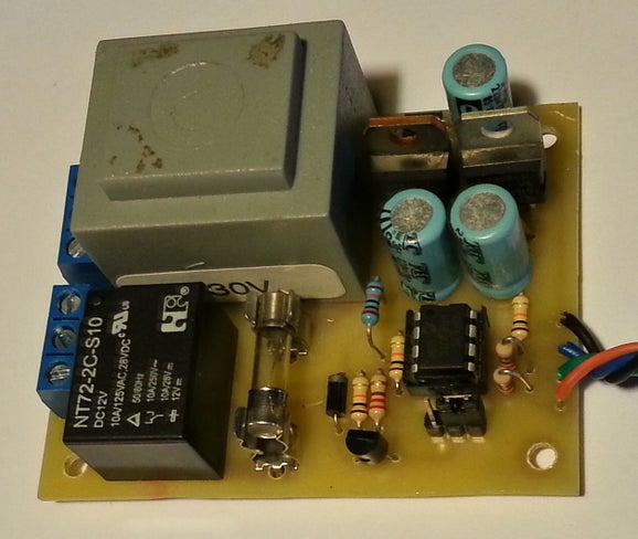
To keep the size small, I decided to construct the timer on PC Board. All components, except the LEDs and buttons are fitted to the PC board.
After the board was assembled and tested, the solder side of the PC Board was treated with clear lacquer to increase the electrical insulation of the mains wiring.
Note the mini jumper just below the PIC 12F675. This jumper is used to select between 50Hz or 60Hz.
Attachments
Step 5: Assembly
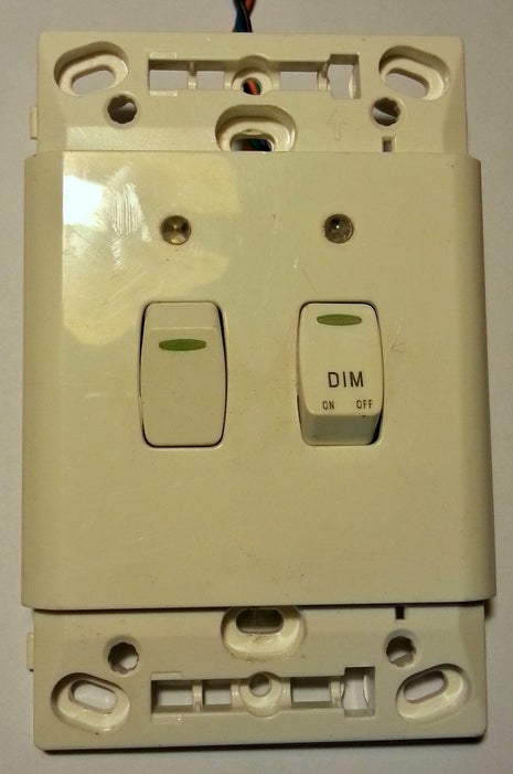
The project is housed inside a plastic light switch box. There are two switches:
The left switch is a standard On/Off light switch used to turn the unit on or off.
The right switch is a Bell of Dimmer switch, which is a spring loaded push button. This button is used to start or stop the bypass timer.
The two LEDs are mounted above the switches for indication.
The unit was then connected to my existing electrical Lights/Plugs, and the output connected to a multiplug.
Step 6: Setting of Timers
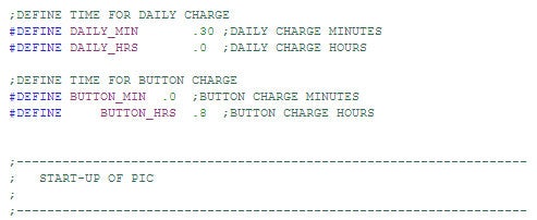
The code supplied, will turn on the relay for 30 minutes every day. Or if the bypass is pressed, the timer will turn on for 8 hours, then return to normal daily charging.
This times can be adjusted in the code as required.
See attached image.
Step 7: Using the Timer
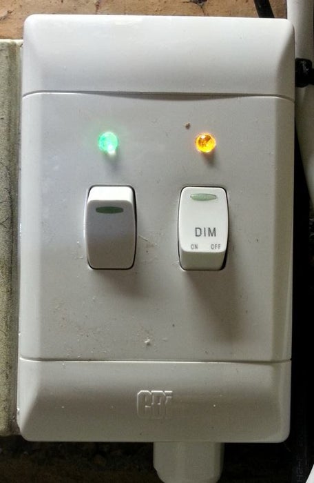
Simply plug your chargers and electrical power tools into the multiplug.
Turn on the system with the power switch. Both LEDs will turn on. This will indicate that the power is on, and the tools are charging. After 30 minutes, the charging LED will turn off, together with the chargers. The chargers will be turned on every day for 30 minutes.
After you used the power tolls, simply plug them back into the charger, and press the Charge button. The Charge LED and chargers will now stay on for 8 hours. After 8 hours, the chargers will turn off automatically, and continue with normal daily charging of 30 minutes.
Pressing the Charge button while charging, will turn off the chargers.
Source: Automated Power Tool Charger
- How does the device maintain battery charge when tools are not used?
The device automatically turns on for 30 minutes every day to keep batteries fully charged. - Can I extend the charging time if the batteries are drained?
Yes, pressing the bypass button extends the charging cycle to 8 hours before resetting to the daily 30-minute mode. - What method is used for accurate long-term timing in this project?
The circuit uses the AC power line frequency (50Hz or 60Hz) to generate a precise pulse count for the timer. - How do I select between 50Hz and 60Hz power lines?
You must set the mini jumper located below the PIC 12F675 chip to match your local power frequency. - What happens if I press the charge button while the chargers are already running?
Pressing the button while charging will turn off the chargers immediately. - Does the system require external Real Time Clock components?
No, the design avoids expensive RTC components by utilizing the power line frequency for timing accuracy. - How are the different operational states indicated to the user?
A power LED indicates the unit is on, while a separate charge LED shows when the charger is actively running. - Can the default charging duration be changed?
Yes, the 30-minute daily and 8-hour override times can be adjusted directly within the software code.
Related projects
Implementing Smart Cooling Control for Induction Heaters with PIC Microcontrollers
Today, induction heating powers countless industrial processes like melting, heat treatment, and welding, plus everyday appliances like cooktops. Its key advantages? High...
Power & BatteryIntegrating Solar Power: Microcontroller-Based Approaches for Domestic Electricity
Abstract: Microcontrollers have found extensive application in endeavors aimed at reducing power consumption. The availability of microcontroller development tools has made them...
Power & BatteryEfficient Power Generation with Microcontroller-Controlled Thermoelectric Generators
INTRODUCTION The global demand for electrical energy continues to rise steadily, necessitating a shift towards renewable energy sources as traditional fossil fuels...
Power & BatteryOptimizing Performance: A Guide to Stacking Precision Power Supplies
1. Introduction Statement of Purpose Our project selection stems from the recognition that power supplies represent a crucial and costly aspect of...
Power & Battery10 Mistakes with Hiring a Home Solar Installer and How to Avoid Them
Are you thinking about installing a home solar system? If so, then you're on the right track. Hitting the pavement for the...
Power & Battery · PIC18F252BATTERY CHARACTERIZER using PIC18F252
Introduction This circuit is a battery characterizer that applies a fixed load to a charged NiCad or NiMH cell and measures milliamp-hour...

Muhammad Bilal
I am a highly skilled and motivated individual with a Master's degree in Computer Science. I have extensive experience in technical writing and a deep understanding of SEO practices.