Summary of An Arduino me-too-alike for PIC16F873A
This article introduces a custom PIC microcontroller development board designed to replicate the Arduino footprint, enabling compatibility with existing Arduino shields. The author created this solution because no open-source standard exists for PIC boards, despite the popularity of AVR-based Arduino add-ons. The project utilizes a PIC16F873A chip and supports programming via ICSP or a TinyBld boot-loader with an FTDI USB lead.
Parts used in the Pequeno Board:
- PIC16F873A Micro-controller
- Double-rows of pin-headers (2 sets of 8 top, 2 sets of 6 bottom)
- Microchip ICSP protocol interface
- TinyBld boot-loader
- FTDI RS232-TTL USB lead
- Printed Circuit Board (PCB) design
We’ve all done it – looked sideways with not a little envy at a range of add-ons for a power tool, and wished that they were available for the one we bought.
There is no ’standard’ footprint for a PIC Micro-controller development/experimental board. Vendors have chosen to provide their own ‘take’ in each case, and who can blame them, selling ‘add-ons’ for a proprietary board increases revenue streams.
Given the maturity of the PIC Micro-controller, one would have thought an ‘Open Source’ standard board for experimenters might have been developed, but no, not yet. I’m as guilty as anyone else, tending to re-vamp and tweak my designs almost on a whim – but that’s another story.
Recently the Arduino project for the AVR Micro-controller was launched, and has become an immediate hit with experimenters and educators alike, with a large number of add-on/plug-in ’shields’ developed and available cheaply, not just by private vendors but also Open Source.
This has probably tempted some putative users of the PIC, to plump for the AVR offering instead, and who can blame them?
Back in 2004 when I again picked up the soldering iron after what seems a lifetime of programming the PC, I examined both the PIC and AVR controllers and decided to use the PIC – it was cheaper, there was more choice of devices, blah, blah. That’s not to say I have any negative criticism for the AVR controllers – I haven’t. But they offer me nothing I have already got in the PIC, and I now have 7 years of PIC development behind me.
This post briefly documents a small PIC Microcontroller development board that mimics the Arduino almost exactly – so that add-ons (’shields) developed for the Arduino can be used on a PIC Micro-controller. All printed circuit designs for the boards are available in the downloads section at the end of the post, together with software to test out the board.
As is my policy, I will try not to repeat stuff here that is already available elsewhere on-line, other than to give an overview, nor give long lists of links which have a habit of disappearing. If you are not already familiar with the Arduino, and the Arduino Shield designs, then swot up on them elsewhere.
The Arduino Shield.
Take a look at the layout of the following PCB which is freely available on-line:
Now concentrating mainly on the double-rows of pin-headers, there are 2 sets of 8 to the top of the picture, and 2 sets of 6 to the bottom. Moving clockwise from the 1st pin at the top, this is marked ‘AREF’, and the next ‘GND’. The rest of the top rows of pins are marked ‘Digital I/O’. Moving (clockwise) to the bottom row, the first rows of pins are marked ‘Analog In’, and numbered 5 thru 0. The next row of 6 are marked ‘VIn’, ‘GND’, ‘5V’, ‘3V’, and ‘RST’.
All of the pins are just simply what they say, and the ‘RST’, ‘Analog’, ‘AREF’, and ‘Digital’ can all be provided by a 28-pin PIC Micro-controller. On the controller board itself, you will probably want a means of programming the PIC without having to remove it from the board each time.
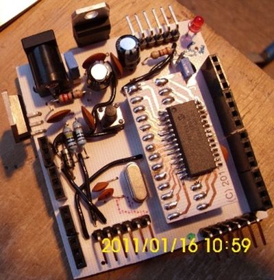
I’ve chosen to provide 2 distinct methods, Microchip’s tried and tested ICSP protocol, and also a boot-loader protocol based on the use of the TinyBld boot-loader and an FTDI RS232-TTL USB lead. My Pequeno board (Geddit?) layout is shown in the next picture, and is not to scale so that you can clearly see the various items as these are discussed.
For more detail: An Arduino me-too-alike for PIC16F873A
- Why was this specific PIC board developed?
To mimic the Arduino layout so that Arduino add-on shields can be used on a PIC microcontroller. - Does a standard open-source board exist for PIC microcontrollers?
No, there is currently no open-source standard board for experimenters using PIC microcontrollers. - What are the two methods provided for programming the PIC?
The board supports Microchip's ICSP protocol and a boot-loader protocol using TinyBld. - How many pin-header sets are located at the top of the PCB?
There are 2 sets of 8 pin-headers at the top of the picture. - Which pins are marked as Analog In on the bottom row?
The first rows of pins on the bottom are marked Analog In and numbered 5 through 0. - Can the RST, Analog, AREF, and Digital pins be provided by a 28-pin PIC?
Yes, all of these pins can be provided by a 28-pin PIC microcontroller. - What software is included with the project?
Software to test out the board is available in the downloads section alongside the printed circuit designs. - Is the author critical of AVR controllers?
No, the author states they have no negative criticism for AVR controllers.